
TM 5-3820-233-12/2
d. Divide the circumference of the pulley into four equal
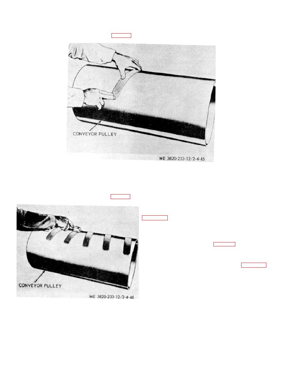
e. Start at center of pulley and apply short lengths of
sections an determine the necessary positioning of lagging
lagging toward both edges. Do not cover connecting cracks
to be applied at an angle on the pulley surface (fig. 4-45).
of pulley.
Figure 4-45. Position lagging.
f. Use a hand roller and rubber mallet to remove air
4-55. Side Conveyor Winch
pockets or bubbles before adhesive has become hardened.
a. General. The rock and sand conveyor may be
Apply roller pressure at center of each strip and roll or
folded for transport. Each conveyor has a pulley, cable and
pound firmly from center of strip towards ends (fig. 4-46).
winch arrangement which is used to fold the conveyor. This
arrangement is identical for both side conveyors.
b. Removal and Disassembly. For removal and
disassembly of the winch assembly arrangement, refer to
c. Inspection.
(1) Inspect winch cables for wear and fraying.
(2) Inspect all parts for excessive wear and
damage.
(3) Inspect shaft (36, fig. 4-47) for damaged
threads.
d. Repair. Repair is made by replacement of
damaged or defective parts.
e. Reassembly and Installation. Refer to figure 4-47
and reassemble and install the side conveyor winch in
reverse order of removal.
Figure 4-46. Removing air pockets.
4-38

