
TM 5-3820-233-35/1
Figure 17 -Continued.
Replace the cylinder head if warpage is
beyond the limits specified.
(4) Check the clearance between the
valves and valve guides. Replace the guides
if the clearance exceeds 0.006 inch.
(5) Inspect valve seats and injector
tubes for signs of over heating, looseness, ex-
cessive wear or other damage. Replace de-
fective parts.
(6) Inspect the valves for cupped,
pitted, burned or worn conditions. Grind the
valves and reseat the inserts to an angle of
30 degrees. Replace parts as necessary.
(7) Inspect the valve springs for exces-
sive wear and replace as necessary.
(8) Inspect the cylinder head surface for
pitting, scratches, or other damage. Resurface
the head or replace as necessary.
e. Reassembly
(1) Reassemble the cylinder head in the
reverse numerical sequence as illustrated on
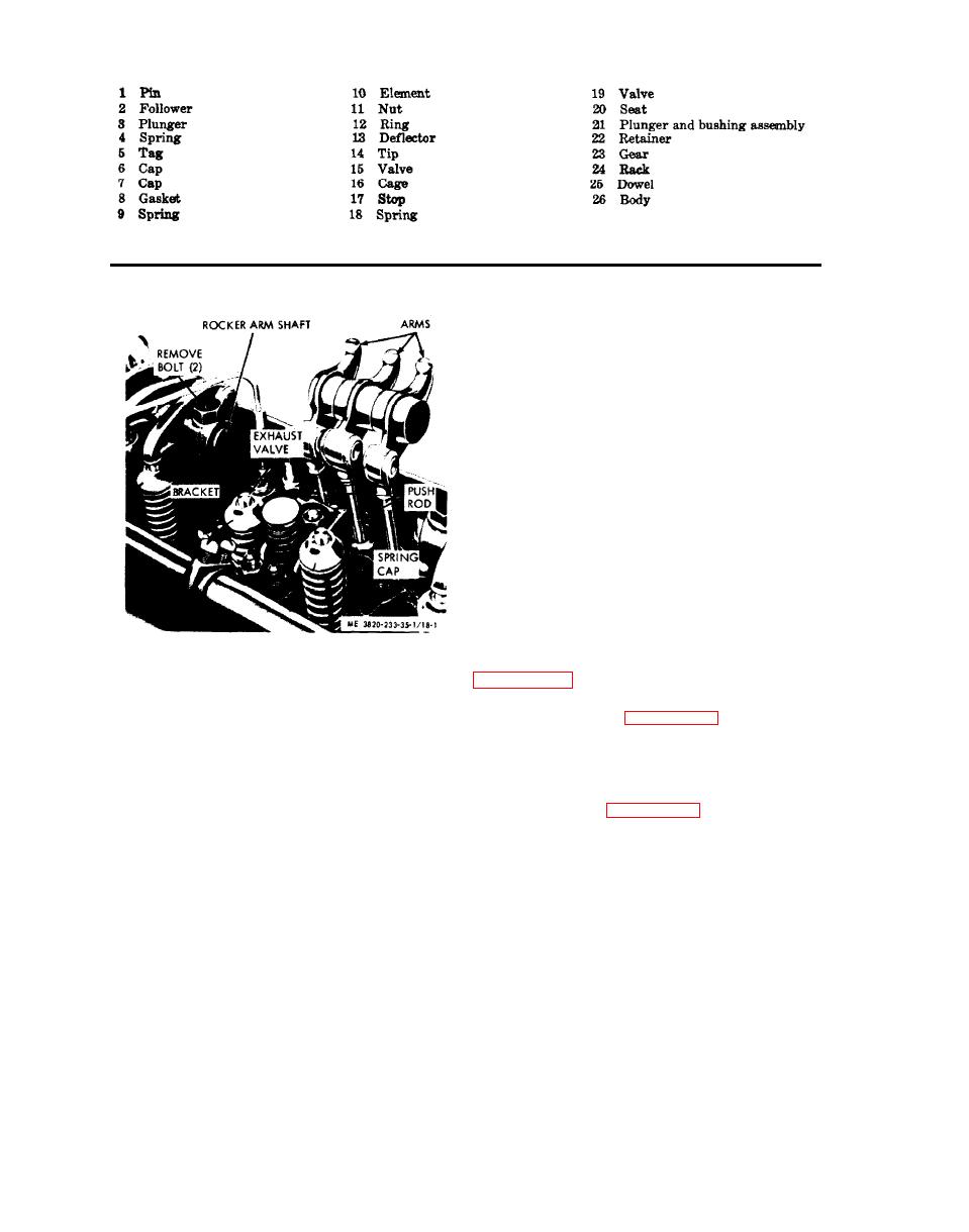
STEP 1. FOLD BACK ROCKER ARMS.
STEP 2. REMOVE ROCKET ARM SHAFT AND
BRACKETS.
(2) Follow the cylinder head tightening
STEP 3. DISCONNECT PUSH ROD FROM
sequence shown on figure 19-3. Torque head
ROCKER ARMS.
bolts to 175-185 foot-pound.
STEP 4. REMOVE ROCKER ARMS,
(3) Install the rocker arms and shafts
(para 41).
installation
f. Installation
(1) Refer to figure 19-1 and install the
d. Cleaning, Inspection, and Repair
cylinder head.
(1) Clean all parts with an approved
(2) Complete the cylinder head installa-
cleaning solvent and dry thoroughly.
tion by reversing the instructions outlined
under "Cylinder Head Removal."
(2) Inspect the cylinder head for cracks
(3) Adjust the exhaust valves and time
or damage. Replace a cracked or damaged
the injectors (Operator's Manual).
cylinder head.
(3) Check the bottom of the cylinder
43. Engine Oil Pan
head for warpage. The warpage limits are as
follows:
a. General. The engine oil pan is located
at the bottom of the engine and is secured
Maximum Longitudinal Warpage----0.008 inch
Maximum Transverse Warpage------0.004 inch
by twenty six bolts. The oil pan serves as a

