
TM 5-3820-233-35/2
STEP 1. ATTACH A SUITABLE LIFTING
TO POWER TAKEOFF ASSEMBLY
STEP 2 ENGAGE THE CLUTCH
STEP 3. REMOVE POWER TAKEOFF
MOUNTING BOLTS.
STEP 4. INSTALL TWO OF THE MOUNT-
ING BOLTS IN HOLES "A", AND
PUSH ASSEMBLY FROM FLY-
WHEEL HOUSING.
STEP 5. PULL POWER TAKEOFF STRAIGHT BACK
FROM ENGINE
Figure 26-1. Power takeoff, removal and
installation.
(5) Refer to the Operator's Manual and install
the muffler and air cleaner.
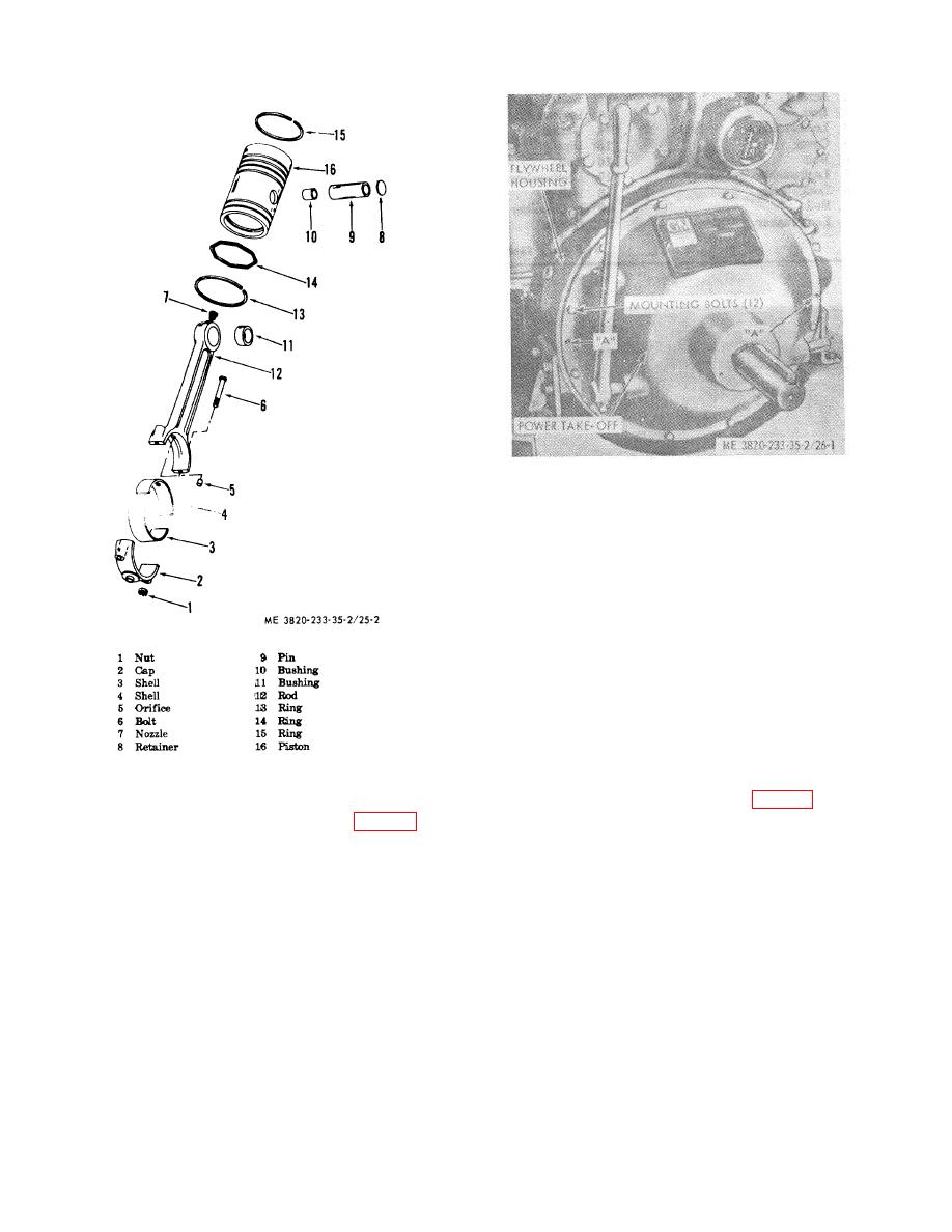
Figure 25-2. Connecting rod and piston.
(6) Install the power unit (para 23).
(7) Fill the cooling system.
(3) Install the radiator assembly (para 33).
50. Fan Pulley and Hub Assembly
(4) Refer to the Operator's Manual and install
a.
General.
The fan pulley and hub
the hoods, side panels, and tie rods.
assembly is mounted on the engine balance weight
cover. The assembly supports the fan and provides
adjustment for the fan belts.
b. Removal and Disassembly
(1) Refer to the Operator's Manual and
remove the muffler and air cleaner.
(2) Refer to the Operator's Manual and
remove the hoods, side panels, and tie rods
(3) Remove radiator inlet hose.
3-38

