
TM 5-3820-233-35/2
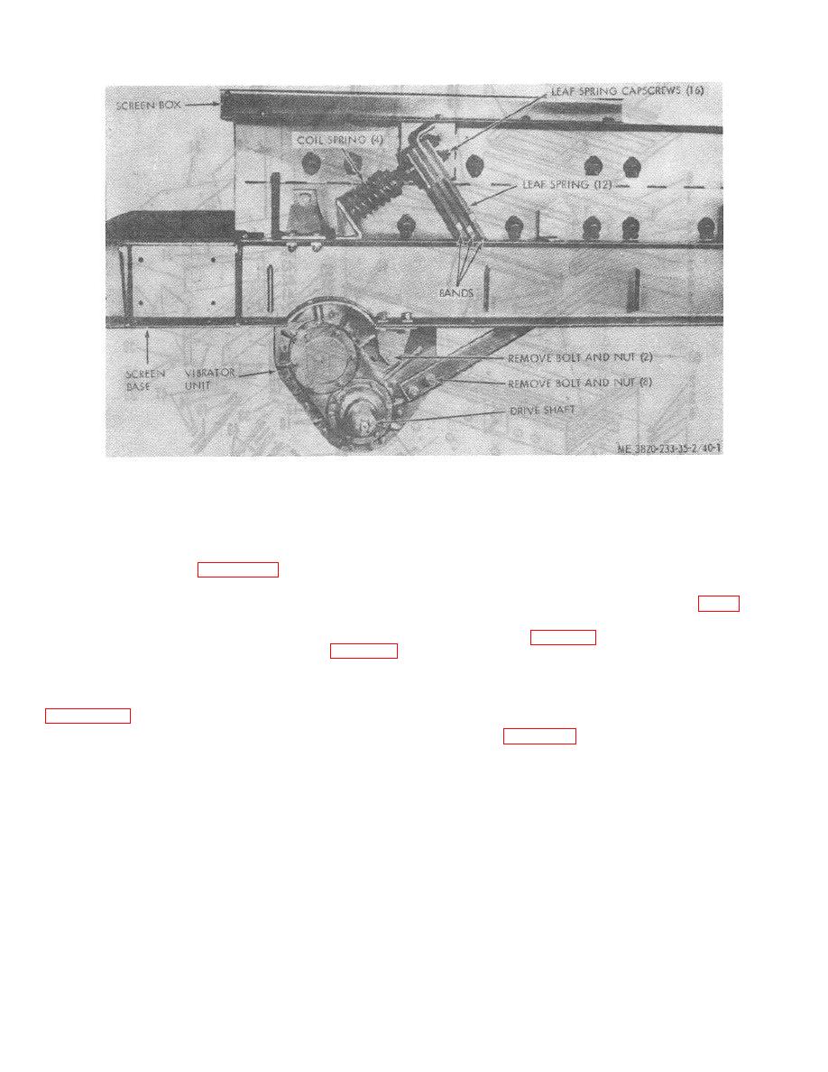
Figure 40-1. Vibrating screen assembly.
(k) Measure for a minimum 0.010
(d) Remove cover (8), gasket (9), and
clearance between the rotating seal (30) and the fixed
end plates (17).
seal (34).
(e) Remove both timing gears using the
(I) Refer to the Operator's Manual for
Special Tools shown on figure 40-7. Turn driven shaft
bearing lubrication instructions.
until keyway is at bottom of shaft. Hold shaft in this
position while removing gear. This will prevent the shaft
(m) Install the screen pulley (fig. 8).
from "swinging free" when gear is removed. Repeat
(n) Coat the bolt circles on inner side of
procedure for remaining gear.
back plate (24, fig. 40-3) with nonhardening gasket
(f) Remove back plate (24, fig. 40-3)
sealant. Install gaskets (25) to back plate.
and gaskets (25).
(o) Apply liquid sealant to back plate
(g) Install bearing into housing. Press
mounting screw threads. Install back plate and torque
bearing onto drive shaft using the Special Tools shown on
mounting screws (22) to 25 lb. ft. Install locking wire (21).
(p) Install gears and align timing marks
illustrated on figure 408, to prevent shaft from moving
as shown on figure 40-8.
laterally.
(h) Press bearing into the housing until
Note.
the inner race of bearing seats firmly against inner
Make sure timing marks are correctly
rotating seals.
alined before installing keys in Step q.
(i) Remove long mounting tool and
holding tool. Install fixed seal (3-1, fig. 403).
(q) Rotate the timed gears until the gear
(j) Install rotating seal (30).
and shaft keyways are aligned. Drive keys into keyway.
4-27

