
TM 5-3820-233-35/2
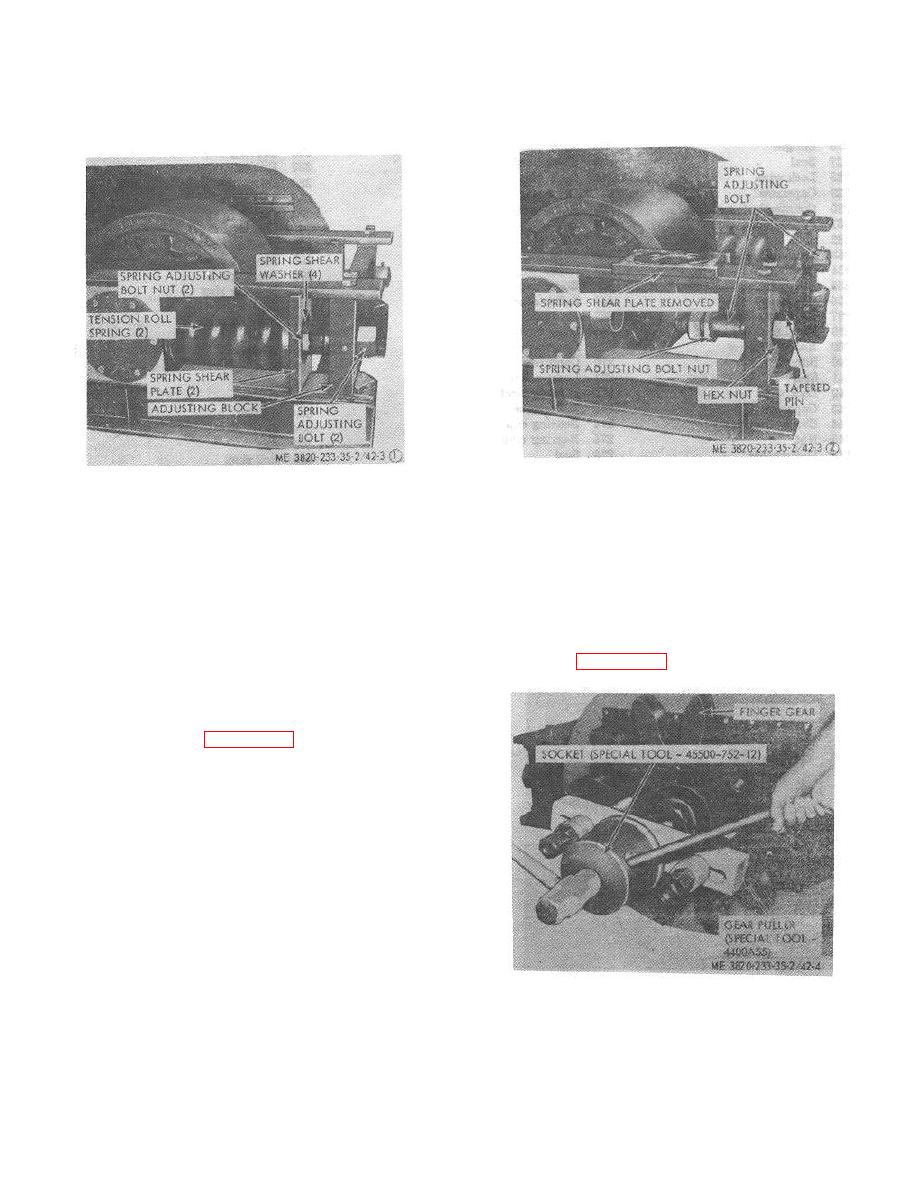
STEP 4.
SLIDE SPRING SHEAR PLATE
STEP 1.
TURN SPRING ADJUSTING BOLT
FORWARD UNTIL IT CAN BE RE-
CLOCKWISE UNTIL THE SPRING
MOVED FROM THE CRUSHER.
ADJUSTING BOLT NUT IS CLEAR
STEP 5.
REMOVE THE SPRING ADJUSTING
OF THE SPRING SHEAR PLATE.
BOLT NUT.
STEIP 2.
REMOVE THE SPLIT SPRING
STEP 6.
REMOVE THE TAPERED PIN AND
SHEAR WASHERS.
HEX NUT FROM THE SPRING
STEP 3.
SLIDE SPRING SHEAR PLATE TO-
ADJUSTING BOLT. REMOVE THE
WARDS THE ADJUSTING BLOCK,
SPRING ADJUSTING BOLT.
THEN REMOVE TENSION ROLL
SPRING.
Figure 42-3 (2)-Continued.
Figure 42-3 (1). Tension roll spring and shear
washer, disassembly and reassembly.
(2) Refer to figure 42-1 and remove slinger
(226) and oil seal (227).
(3) Remove locking wire (228), capscrews
(229), countershaft cap (230) and bearing spacer (231).
(4) Remove the bearing lock nut (232) and
lockwasher (233).
(5) Position bearing lock nut (232) back onto
the shaft until the face of the nut is approximately 1/8
inch away from the inner race of the bearing (234).
(6) With a bar and hammer, drive laterally on
face of lock nut, rotating the point of contact, until the
bearing sleeve (238) breaks loose from the bearing and
sleeve.
(7) Remove the lock nut.
(8) Identify the bearing adapters (237 and
Figure 42-4. Finger gear removal.
251) as to which side of the countershaft
4-46

