
b. Disassembly. Disassemble the handcranking
b. Cleaning and Inspection. Clean and inspect all
assembly as illustrated on figure 16.
parts. Inspect the air cleaner indicator for proper
operation. Replace damaged parts.
c. Cleaning, Inspection, and Repair. Clean and
inspect. Replace or repair worn, damaged, or defective
c. Installation. Install the air cleaner indicator on
parts as necessary.
the air cleaner in reverse of the instructions on figure 14.
d. Reassembly. Reassemble the handcranking
assembly as illustrated on figure 16.
57. Handcranking Assembly
e. Installation. Install the handcranking assembly
a. Removal. Remove the handcranking assembly
on the engine in reverse of the instructions on figure 15.
from the engine as instructed on figure 15.
Section II. FUEL SYSTEM
aids, and the necessary lines and fittings for distributing
58. General
the diesel fuel to the components of the fuel system.
The diesel fuel system consists of a 100-gallon fuel
tank, primary fuel filter, secondary fuel filter, fuel primer,
fuel injector pump, engine speed governor, fuel
injectors, air cleaner, intake manifolds, ether starting
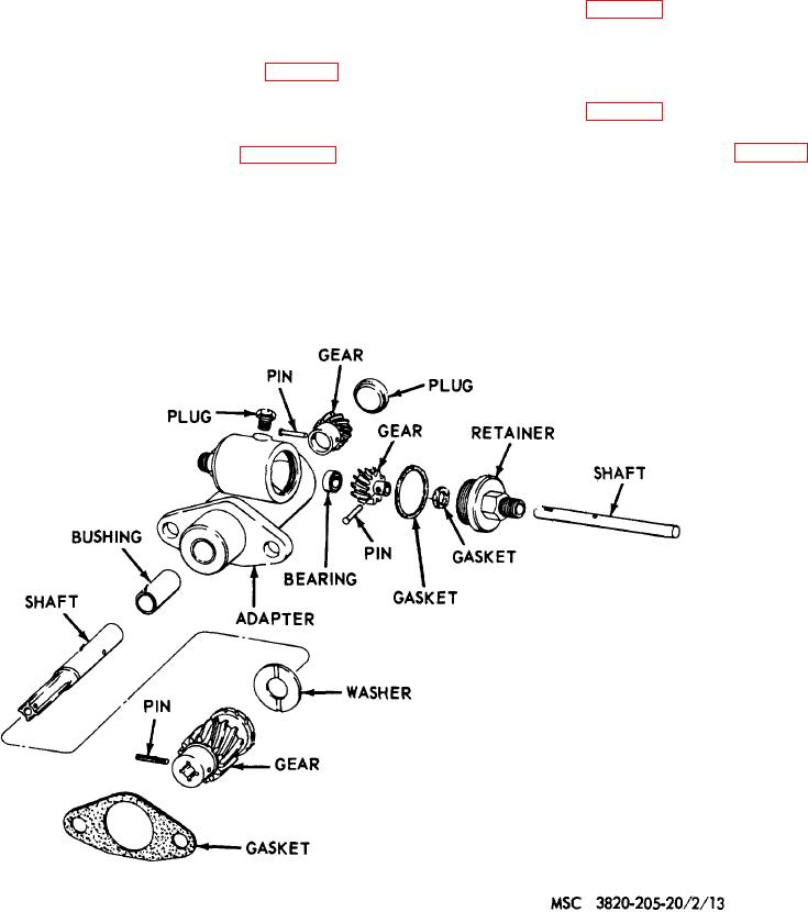
Figure 11. Tachometer drive, exploded view.
AGO 8157A
30