
CHAPTER 5
DOLLY MAINTENANCE INSTRUCTIONS
Section I. DOLLY ELECTRICAL SYSTEM
of the dolly. A wiring harness runs from the connector to
105. General
the rear of the dolly to two taillights and blackout lights.
The dolly electrical system consists of a connector cable
and wiring harness. (Current supplied by the towing
106. Electrical Connector
vehicle is carried by the connector cable to a connector
at the front
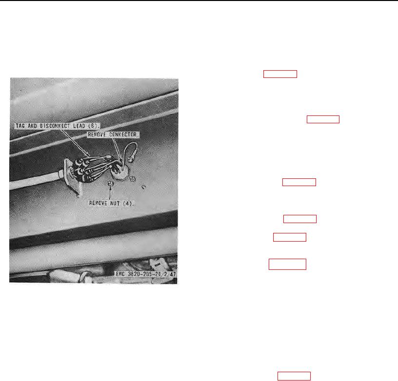
a. Removal. Remove the connector from the dolly
as instructed on figure 51.
b. Cleaning and Inspection. Clean and inspect all
parts. Replace defective connector. Repair defective
wiring.
c. Installation. Install the connector on the dolly in
reverse of the instructions on figure 51.
107. Tail and Blackout Lights and Dolly Electrical
Leads
a. Removal. Remove the tail and blackout lights
and the dolly electrical leads from the dolly as instructed
on figure 52.
b. Disassembly. Disassemble the tail and blackout
lights as illustrated on figure 53.
c. Cleaning, inspection, and Repair. Clean and
inspect all parts. Replace defective parts.
d. Lamp and Lens Replacement. Replace a lamp
and lens illustrated on figure 53.
e. Reassembly. Reassemble the tail and blackout
lights illustrated on figure 53.
f. Installation. Install the tail and blackout lights
and the dolly electrical leads on the dolly in reverse of
the instructions on figure 52.
Figure 51. Electrical connector, removal and
installation.
Section II. DOLLY ASSEMBLY
109. Dolly Assembly
108. General
The dolly assembly consists of a drawbar, lunette, fifth
a. Removal.
wheel, wheels, and wheel bearing assemblies. The
(1) Crib the roll crusher (TM 5-3820-205-10.'1).
dolly is used to carry the front end of the trailer frame
(2) Remove the dolly assembly from the
when the unit is being pulled as a full trailer. The fifth
unit as instructed on figure 54.
wheel includes a jaw-latch mechanism for connecting or
b. Cleaning and Inspection. Clean and in-
disconnecting the dolly assembly from the trailer.
AGO 8157A 76