
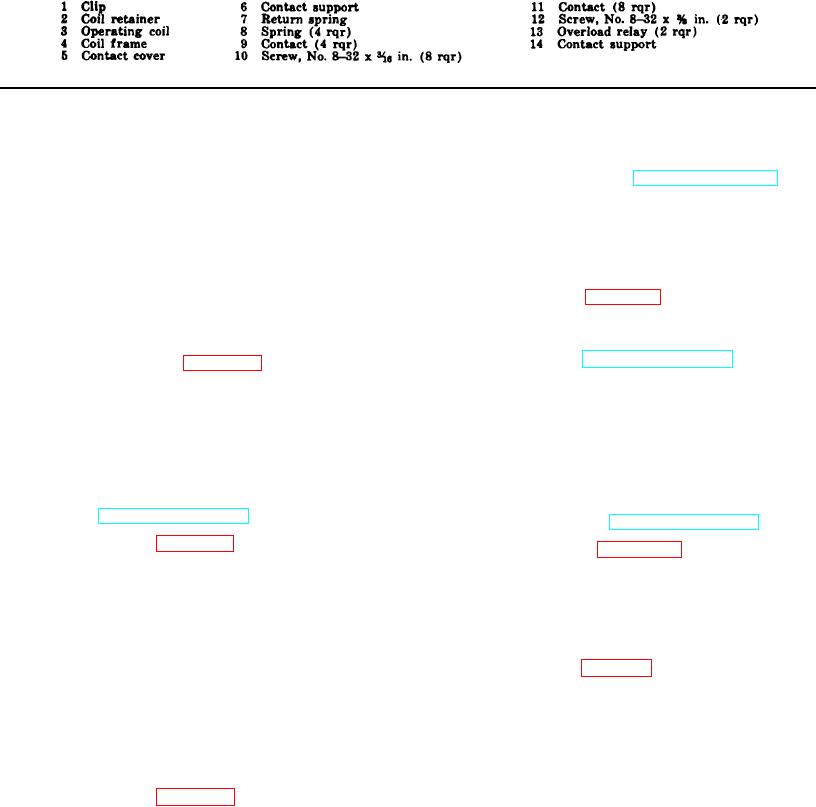
Figure 62-Continued.
Section II. CONTROL PANEL ASSEMBLIES
217. General
(2) Connect all wiring. Refer to tags and
wiring diagram (TM 5-3820-20520/2).
The main control panel assembly contains the
magnetic starter assemblies, circuit breaker, relays,
(3) Install the magnetic starter assemblies
switches, junction blocks, and wiring necessary for
and pushbutton switches (TM 5-3820-205-
controlling the power supply for the various components
20/2).
of the jaw crusher. It is of steel construction and has
b. Installation.
seals around the panel door so it is watertight when
closed. The operator's control panel contains the start
(1) Refer to figure 63 and install the main
and stop switches for the crusher components.
control panel on the unit.
218. Main Control Panel Removal and Disassembly
(2) Position and connect the electric motors
conduit (TM 5-3820-205-20/2).
a. Removal. Refer to figure 63 and remove the
main control panel from the unit.
221. Operator's
Control
Box
Removal
and
Disassembly
b. Disassembly.
a. Removal.
(1) Remove the magnetic starter assemblies
and pushbutton switches (TM 5-3820-205-
(1) Remove the electric conduit (TM 5-3820-
20/2).
205-20/2).
(2) Disconnect and tag all wiring and cables
(2) Disconnect the wiring in the operator's
control box (TM 5-3820-205-20/2).
(3) Refer to figure 64 and disassemble the
(3) Refer to figure 65 and remove the
main control panel.
operator's control box from the unit.
219. Main Control Panel Cleaning, Inspection, and
b. Disassembly.
Repair
(1) Remove the pushbutton switches (TM 5-
a. Cleaning. Clean all parts with an approved
3820-205-20/2).
cleaning solvent and dry thoroughly.
(2) Refer to figure 64 (2) and disassemble the
b. Inspection and Repair. Inspect all parts for wear
operator's control panel.
and damage. Repair or replace as necessary.
222. Operator's Control Box Cleaning, Inspection,
220. Main
Control
Panel
Reassembly
and
and Repair
Installation
a. Cleaning. Clean all parts with an approved
a. Reassembly.
cleaning solvent and dry thoroughly.
(1) Refer to figure 64 and reassemble the
b. Inspection and Repair. Inspect all parts for wear
main control panel in reverse order.
and damage. Repair or replace as necessary.
AGO 3456A
117