
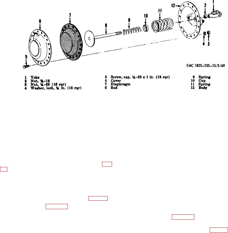
Figure 60. Air chamber assembly, exploded view.
Section II. FRONT AND REAR AXLE ASSEMBLY
b. Inspection and Repair.
206. General
The rear axle assembly consists of two axles, two
(1) Inspect the walking beams for cracks,
walking beams, a center axle and the necessary
breaks, or bends, repair or replace as
hardware to complete the rear axle assembly. The front
necessary.
axle assembly is located under the dolly and fifth wheel
(2) Inspect the axle for bends, wear, or other
assembly. The front axle assembly consists of wheels
damage, replace a bent or defective axle
and axle and supports the front of the crusher.
as necessary.
207. Rear Axle Assembly Removal and Disassembly
(3) Inspect the bushings, clamps, and
a. Removal. Remove the rear axle assembly (par.
clamping ring for excessive wear or
damage. Replace as necessary.
b. Disassembly.
(4) Inspect all mounting hardware for stripped
or damaged threads or other damage,
(1) Remove the air chamber assemblies (TM
replace all damaged parts as necessary.
5-820-206-20/2).
209. Rear Axle
Assembly
Reassembly
and
(2) Remove the brake assemblies (par. 197).
Installation
(3) Refer to figure 61 and disassemble the
a. Reassembly.
rear axle assembly.
(1) Refer to figure 61 and reassemble the
208. Rear Axle Assembly Cleaning, Inspection, and
rear axle assembly in the reverse order.
Repair
(2) Install the brake assemblies (par. 199).
a. Cleaning. Clean all parts with an approved
cleaning
solvent
and
dry
thoroughly.
(3) Install the air chamber assemblies (TM 5-
3820-205-20/2).
AGO 3456A
112