
TM 5-3820-233-12/1
damage and replace if necessary.
4-78. Tool Box
c. Installation. Refer to figure 4-73 and install tool box.
a. Removal. Refer to figure 4-73 and remove tool box
from the support.
b. Inspection. Inspect tool box for excessive wear and
Figure 4-73. Tool box, removal and installation.
disassemble the pintle hook in numerical sequence.
4-79. Pintle Hook
b. Inspection.
Inspect for broken or missing
The pintle hook assembly is fastened to the rear cross
hardware. Replace a defective part.
member of the jaw crusher frame by means of a flanged
c. Installation. Refer to figure 4-74 and reassemble
holder bolted through the frame. It serves to couple the
and install the pintle hook in the reverse order of
dolly to the unit for transportation.
disassembly and removal.
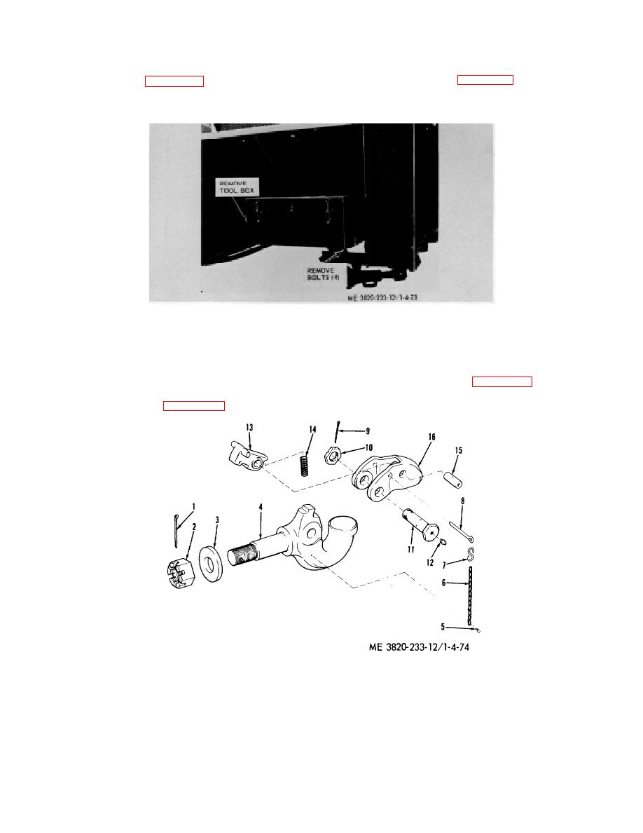
a. Removal. Refer to figure 4-74 and remove and
1 Pin
9 Pin
2 Nut
10 Nut
3 Washer
11 Bolt
4 Hook
12 Grease Fitting
5 Screw
13 Latch
6 Chain
14 Spring
7 Hook
15 Pin
8 Pin
16 Lock
Figure 4-74. Pintle hook, removal and installation.
4-76
