
TM 5-3820-233-35/1
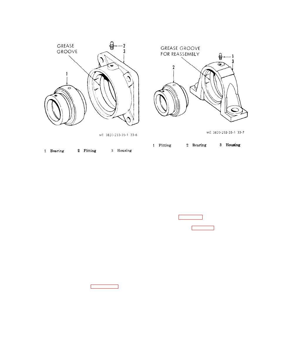
Figure 33-6. Snub roll idler and tail bearing assemblies,
exploded view.
Section V. CONVEYOR DRIVE
(2) Disassemble the speed reducer in the
62. General
numerical sequence as illustrated on figure
The speed reducer located on the head pulley
34-2.
shaft is belt driven from the front counter-
c. Countershaft Bearing Disassembly. Dis-
shaft. The front countershaft is belt driven
assemble the countershaft bearing assemblies
from the jaw crusher flywheel.
(21 and 26, fig. 34-l) in the same manner,
as they. are similar in construction and mainte-
nance procedures (fig. 34-3).
a. Removal and Disassembly
(1) Remove speed reducer from head
d. Cleaning, Inspection, and Repair
pulley shaft (para 27).
(1) Clean all parts with an approved
(2) Remove V-belt (6, fig. 34-l). Re-
cleaning solvent and dry thoroughly.
move nuts (7), lockwashers (8), bevel wash-
(2) Perform a magnetic inspection of
ers (9), and capscrews (10), and remove
the countershaft. Replace a defective shaft.
countershaft support (30) complete with bear-
ings, pulleys, and countershaft attachcd, from
(3) Inspect bearing assemblies for wear,
the truck frame.
scoring, nicks, and chipping. Replace defective
bearing componet parts or the whole assem-
(3) Disassemble the conveyor drive com-
bly if required.
ponents illustrated on figure 34-1.
b. Speed Reducer Disassembly.
(4) Inspect all parts for wear or dam-
(1) Drain lubricant from speed reducer.
age. Repair or replace defective parts.
