
SYSTEMS OPERATION
(90N1-90N6120)
FUEL SYSTEM
Engines with Serial Numbers 90N1-90N6120
The sleeve metering fuel system is a pressure
CAUTION: Diesel fuel is the only lubrication for
type fuel system. The name for the fuel system is
the moving parts in the 'transfer pump, injection
from the method used to control the amount of
pump housing, and the governor. The injection
fuel sent to the cylinders. This fuel system has an
pump housing must be full of fuel before turning
injection pump for each cylinder of the engine. It
the camshaft.
also has a fuel transfer pump on the front of the
injection pump housing. The governor is on the
This fuel system has governor weights, a thrust
rear of the injection pump housing.
collar and two governor springs. One governor
spring is for high idle and the other governor spring
The drive gear for the fuel transfer pump is on
is for low idle. Rotation of the shaft for governor
the front of the camshaft for the injection pumps.
control, compression of the governor springs,
The carrier for the governor weights is bolted to
movement of connecting linkage in the governor
the rear of the camshaft for the injection pumps.
and injection pump housing controls the amount
The injection pump housing has a bearing at each
of fuel sent to the engine cylinders.
end to support the camshaft. The camshaft for the
sleeve metering fuel system is driven by the timing
Fuel from fuel tank (7) is pulled by fuel transfer
gears at the front of the engine.
pump (11) through fuel filter (9). From fuel filter
(9) the fuel goes to housing for fuel injection
The injection pumps, lifters and rollers, and the
pumps (14). The fuel goes in housing (14) at the
camshaft are all inside of the pump housing. The
top and goes through inside passage (20) to fuel
pump housing and the governor housing are full of
transfer pump (11).
fuel at transfer pump pressure (fuel system pres.
sure).
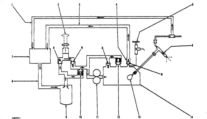
SCHEMATIC OF FUEL SYSTEM
1. Return line for fuel Injection nozzles. 2. Fuel priming pump. 3. Return line for constant bleed valve. 4, Constant
bleed valve. 5. Manual bleed valve. 6. Fuel injection nozzle. 7. Fuel tank. ,8.Fuel Inlet Line. 9. Fuel filter. 10.
Bypass for fuel priming pump. 11. Fuel transfer pump. 12. Fuel bypass valve. 13. Camshaft. 14. Housing for fuel
Injection pumps. A. Check valve. 5. Check valve. C. Check valve. D. Check valve.
4