
COOLING SYSTEM
SYSTEMS OPERATION
(Industrial Engines)
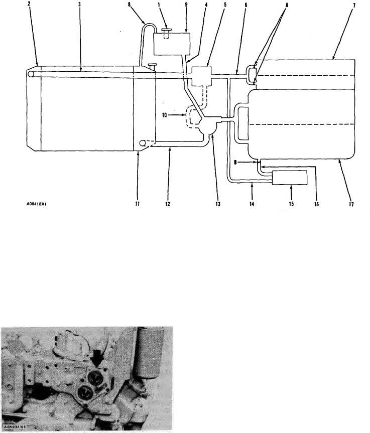
COOLING SYSTEM WITH CROSS FLOW RADIATOR AND SEPARATE SURGE TANK
(Used on Caterpillar Lift Trucks)
1. Radiator cap. 2. Radiator top tank. 3. Radiator top hose. 4. Shunt line. 5. Housing for water temperature
regulators. 6. Return to housing for water temperature regulators. 7. Cylinder heads (two). 8. Vent tube. 9.
Surge tank. 10. Inside bypass. 11. Radiator bottom tank. 12. Radiator bottom hose. 13. Water pump. 14.
Outlet line for oil cooler. 15. Oil cooler. 16. Inlet line for oil cooler. 17. Cylinder block. A. Orifices between
cylinder heads and front cover. B. Orifice in oil cooler outlet.
radiator is made with a left side tank (2) and a right side
Never run an engine unless the water
CAUTION:
tank (11). The surge tank (9) is either a part of right side
temperature regulators are installed. With no water
tank (11) separated by an inside baffle or a tank
temperature regulators in the system the coolant will
separate from the radiator. Vent tube (8) connects the
continually bypass the radiator and the engine will get too
surge tank (9) to the radiator.
hot.
Surge tank (9) has a shunt line (4) that connects to
the inlet of water pump (13). This shunt type system
keeps a positive pressure on the inlet of water pump (13)
at all times. When putting coolant in the cooling system
coolant from surge tank (9) goes through shunt line (4) to
the inlet of water pump (13) and fills cylinder block (17)
from the bottom. By filling the system from the bottom
any air in the system is pushed out through radiator top
tank (2) through vent tube (8) into surge tank (9).
Radiator cap (1) is used to keep the correct pressure
in the cooling system. This pressure keeps a constant
LOCATION OF WATER TEMPERATURE REGULATORS
supply of coolant to water pump (13). If this pressure goes
too high a valve in radiator cap (1) moves (opens) to get
The vertical radiator is made with a top tank (2)
a reduction of pressure. When the correct pressure is in
above the core and a surge tank (9) either above or
the cooling system the valve in radiator cap (1) moves
separate from the top tank. Vent tube (8) connects
down (to the closed position).
radiator top tank (2) and surge tank (9). The cross flow
23