3208 INDUSTRIAL AND MARINE ENGINES
DISASSEMBLY AND ASSEMBLY
FUEL INJECTION NOZZLES
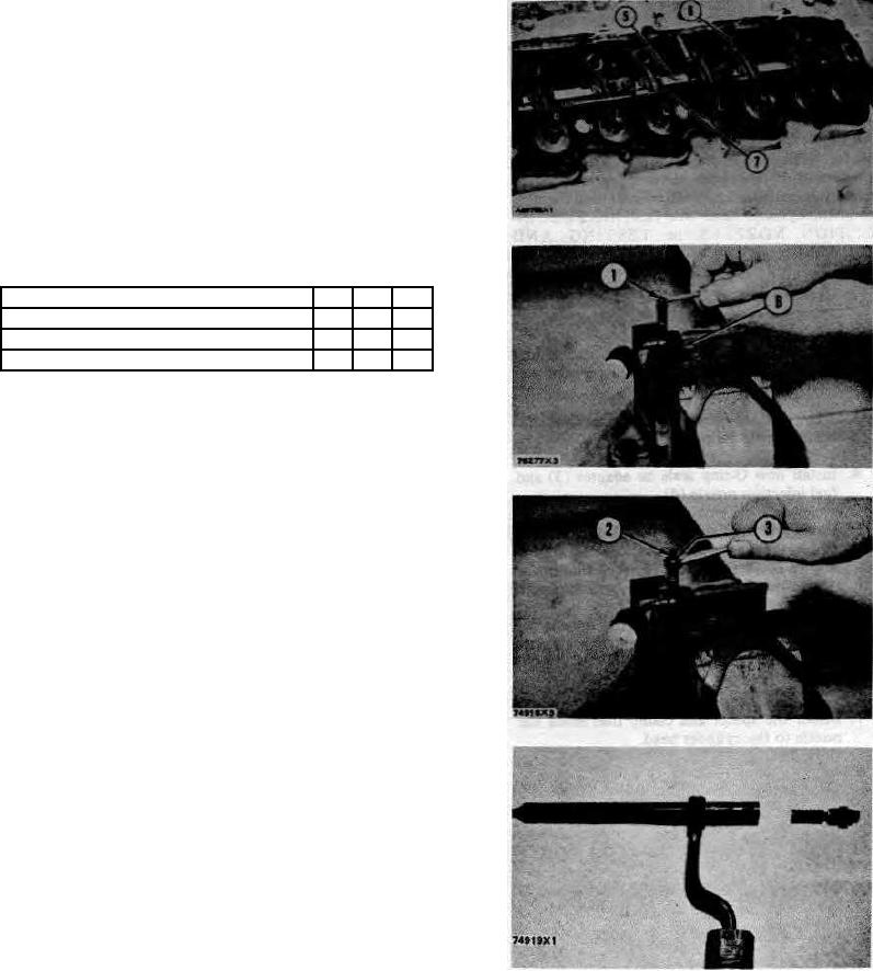
8. Put rocker shafts (5) and fuel return manifolds
(7) in position and install the locks and bolts.
Tighten the bolts to a torque of 18 5 lb.ft. (2.5
0.7 mkg).
9. Make adjustments until the intake valve
clearance is .01-5 in. (0.38 mm) and the
exhaust valve clearance is .025 in. (0.64 mm).
Tighten nuts (6) to a torque of 24 5 Ib.ft. (3.3
0.7 mkg).
end by:
a) install valve covers
DISASSEMBLE FUEL INJECTION NOZZLES
(9L7883 Nozzles)
15-1254
Tools Needed
A
B
C
8S2242
Nozzle Test Group
1
8S2250
Nozzle Holding Tool
1
5P958
Valve Retractor
1
start by:
a) remove fuel injection nozzles
NOTE: Do not disassemble any nozzle until testing has
shown that disassembly is needed. Check each nozzle
with tool (A) for leakage, opening pressure, and the
shape and amount of fuel(spray pattern) coming out of
the nozzle. Do not clean or make an adjustment to any
nozzle that has a large (excessive) amount of return
leakage. Excessive return leakage can be an indication
of nozzle failures that can not be corrected with an
adjustment or cleaning and can cause engine damage.
See TESTING 9L7883 FUEL INJECTION NOZZLES in
TESING AND ADJUSTING.
CAUTION: Keep the work area and all tools extra
clean. Be careful not to cause damage to the parts
during disassembly and assembly of the nozzles.
1. Put the nozzle in tool (B). Put tool (B) and the
nozzle in a vise. Do not put any part of a nozzle
directly in a vise. Loosen locknut (1).
2. Loosen adjusting screw (2) approximately three
turns. Loosen pressure screw (3).
3. While holding the nozzle in one hand, tilt the
nozzle and remove the pressure adjusting screw
and locknut, shims, spring, seat, and valve.
60

