
3208 INDUSTRAIL AND MARINE ENGINES
DISASSEMBLY AND ASSEMLBLY
CRANKSHAFT AND GEAR
9.
Remove the bearing caps and measure the
thickness of the wire.
The main bearing
clearance must be .002 to .005 in. (0.05 to 0.13
mm). The maximum permissible clearance is
.006 in. (0.15 mm).
10. Put clean engine oil on the bolt threads, washer
faces and lower halves of the main bearings.
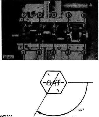
Put the bearing caps in position and install the
bolts. Tighten the bolts in number order as
follows:
a)
Tighten bolts 1 through 10 to a torque of 30
3 lb. ft. (4.1 0.4 mkg).
b)
Put a mark on each bolt head and bearing
cap. Tighten bolts I through 10 120 5
more.
11. Install indicator group (A) and check the end
play of the crankshaft.
The end play is
controlled by the thrust bearing on No. 4 main
bearing. The end play with new bearings must
be .006 .003 in. (0.15 0.08 mm). The
maximum permissible end play with used
bearings is .014 in. (0.36 mm).
end by:
a) install
timing gear cover and oil pump
b) install
c) install
valve lifters
d) install
flywheel housing
94