
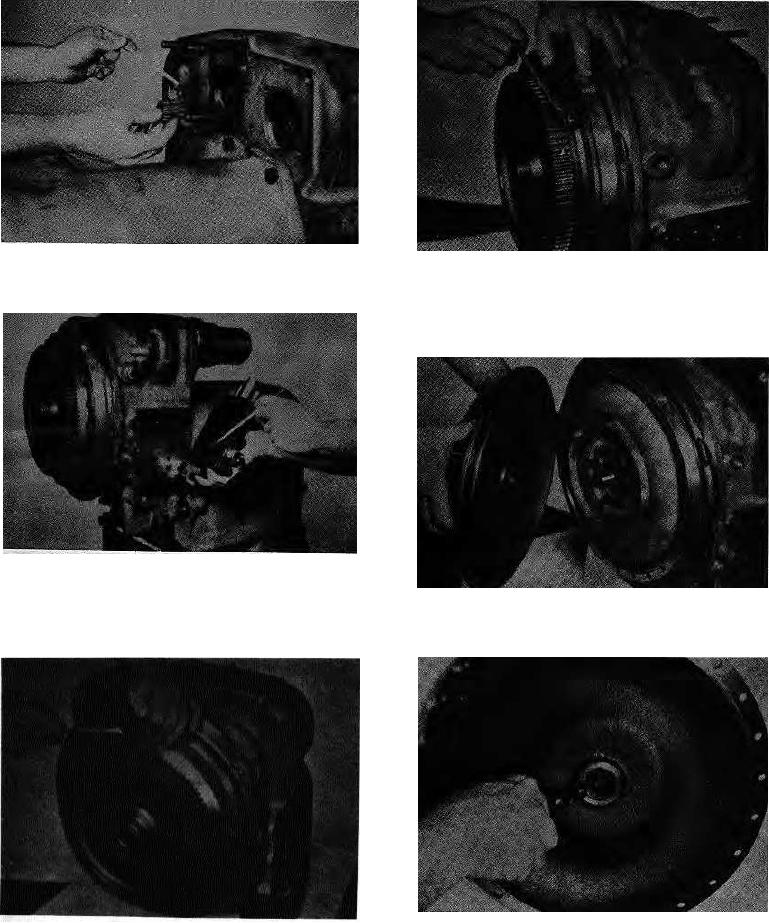
Figure 5
Figure 8
Remove pump drive sleeves.
Install two bolts in threaded holes 180 apart to remove
cover from impeller. NOTE: Some units may have pry
slots instead of threaded holes.
Figure 6
Remove control valve bolts and washers. Remove
control valve. Use caution as not to lose detent springs
Figure 9
and balls.
Remove impeller cover.
Figure 10
Figure 7
If impeller cover bearing is to be replaced remove
Remove impeller cover bolts.
trainer ring. Pry bearing from pocket.
-2-