
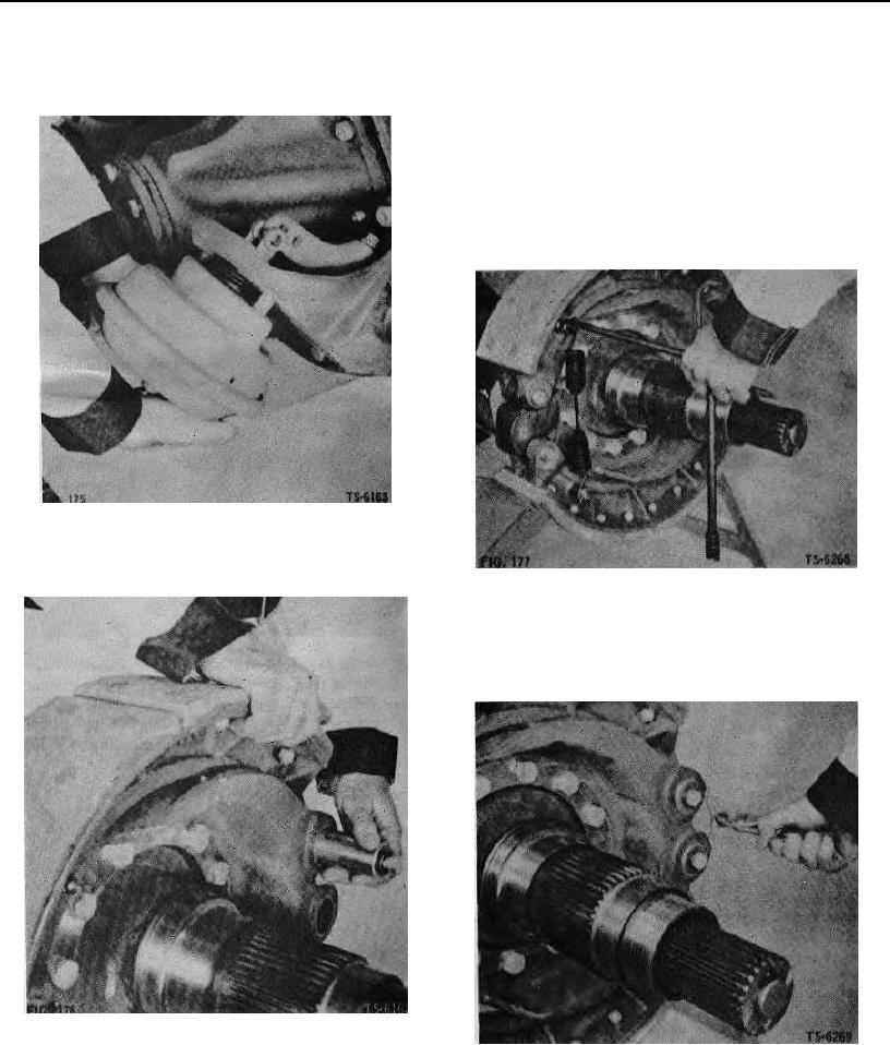
20. Position air chamber on air chamber bracket (Fig.
22. install brake shoe return spring (Fig. 177). Before in-
175). Secure with nuts and lockwashers. Tighten
stalling spring, make sure that slack adjusters are ad-
nuts to specified torque. Secure clevis of brake
justed to allow brake shoes to come together as
chamber to slack adjuster with pin and coffer pin.
closely as possible so that spring tension will be at a
minimum during installation. Install spring anchor pin
washers and cotter pins.
CAUTION: Do not use pliers with serrated jaws to as-
semble brake spring. Do not use any tool which will
nick or score spring. This will cause early failure. Tool
shown is broke pliers which has provisions on end of
handle for installing spring.
21. Position broke shoe on spindle support. Retain brake
shoe by inserting brake shoe anchor pin (Fig. 176).
Install second brake shoe in same manner.
23. Lock brake shoe anchor pins with anchor pin set
screws. Lockwire set screws (Fig. 178).
NOTE: On some axles, brake anchor pins are held
in place with retaining plate, bolt, and lockwasher.
Tighten bolt to specified torque.
50