TM 5-3820-205-10-2
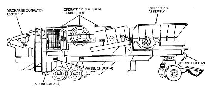
Figure 18. Jaw crusher prepared for transport.
g.
Raise and secure the leveling jacks in transport position in reverse of the instructions on figure 4, and stow jack
pads in the toolbox.
h.
Remove jaw crusher electric cable connector and airbrake hoses from the toolbox and install on jaw crusher (fig.
1).
Caution: Do not exceed 20 mph on good hard surface road or 10 mph on secondary roads or cross-country
when towing the jaw crusher.
i.
Attach suitable towing vehicle to the jaw crusher. Remove the wheel chock (fig. 1) and stow them in the bracket
on the frame (fig. 18).
j.
If the movement of the new worksite is a short distance and the equipment could be safely towed over existing
roads and bridges with sufficient safe clearances, it is not necessary to perform all of the above operations for
transporting the jaw crusher to its new worksite. Follow the instructions in subparagraphs a, b, c, g, h, and i for this type
of movement.
k.
Install and set-up the jaw crusher (para 9).
Section II. CONTROLS AND INSTRUMENTS
11. General
This section describes, locates, illustrates, and furnishes the operator or crew sufficient information about the
various controls and instruments for proper operation of the jaw crusher.
12. Controls and Instruments
Caution: Operator's switch boxes must be properly closed and sealed to prevent water from entering the box
and causing switches and controls to corrode and become unserviceable. All control boxes should be
examined to assure that doors are properly sealed and closed tight.
The purpose, location, and use of the controls and normal readings of the instruments and gages are illustrated on
figures 19-29.
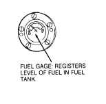
Figure 19. Fuel gage.
18