
first mile, fifth mile, and tenth mile retorque inner and
(3) Clean and inspect wheels and tires.
then outer nuts to 500 to 600 ft-lb. If at the tenth mile
Replace defective wheels and tires.
torque value has dropped below 400 ft-lb, remove
Repair tires and tubes as instructed in TM
wheels, investigate, and repeat entire procedure.
9-1870-1.
Caution
c. Installation.
A trestle (Motor Vehicle Maintenance,
(1) Install inner wheel on hub.
5 ton) will be used in final torquing
Note. Number the studs 1 to 6.
operations, taking care that drive
(2) Install inner capnuts on studs 1 and 4 and
extensions are parallel to the ground
torque to 150 to 200 ft-lb.
at all times.
(3) Install the remaining capnuts and torque
112. Wheel Bearing and Hub Assemblies
No. 2, 5, 3, and 6 to 500 to 600 ft-lb in
a. Removal and Disassembly.
that order. Retorque Nos.
(1) Remove the dolly wheels (para. 111).
1 and 4 to 500 to 600 ft-lb.
(2) Remove and disassemble wheel bearings
(4) Install the outer wheel assembly, making
as illustrated on figure 57.
sure that the outer wheel valve stem is
b. Cleaning, Inspection, and Repair.
opposite the inner valve stem.
(1) Clean and inspect all parts. Replace
(5) Install two outer nuts on opposite studs
defective parts as necessary.
(without the washers installed) and torque
(2) Service the wheel bearings as instructed
to 150 to 200 ft-lb.
(6) Install the four remaining outer nuts (with
c. Reassembly and Installation.
washers installed) and torque to 500 to
(1) Install the bearings and hub on the axle as
600 ft-lb in the sequence outlined above.
illustrated on figure 57.
(7) Remove the two outer nuts (5 above) and
Note. Install hubs with right-hand studs
reinstall with washers and torque to 500 to
on right side of the vehicle and hubs with
600 ft-lb.
left-hand studs on left side of the vehicle.
(8) Remove the dolly from the blocks using a
(2) Install the wheel bearing adjusting nut.
suitable lifting device and road test
Screw the nut against the bearing as the
approximately 10 miles. After
wheel is revolved. Be sure there is
sufficient
clearance
between
the
brakeshoe and drum so brakeshoe drag
will not interfere with the bearing
adjustment.
(3) Tighten the adjusting nut to 50 ft-lb torque
while the wheel is being rotated. Rotate
the wheel in both directions to position the
bearings correctly.
(4) Back-off adjusting nut 1/6 to 1/4 turn, and
install the adjusting nut lockwasher. If the
holes in lockwasher do not fit dowel
protruding from adjusting nut, the washer
may be removed and turned over, which
changes hole locations.
(5) Install the outer locknut and torque to 250
to 400 ft-lb.
Note. The use of an impact wrench is
discouraged; however, if used, the final
torquing
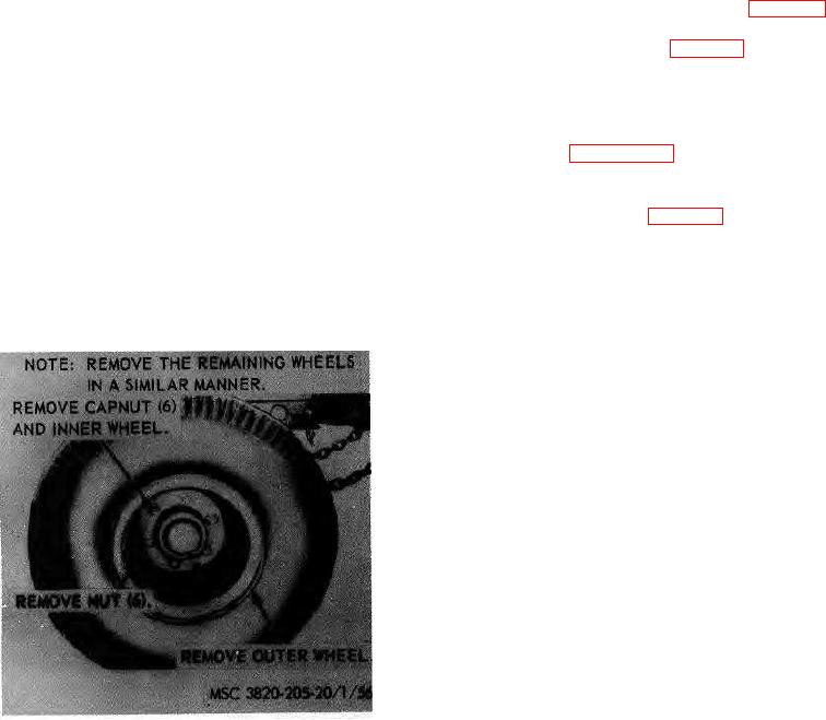
Figure 56. Dolly wheels, removal and installation
AGO 8157A 83