
will be accomplished by hand using a smooth downward
114. Drawbar
effort.
a. Removal.
(6) Install the dolly wheel (para. 111).
(1) Remove flexo-stick assembly from the
drawbar (TM 5-3820-205-10/1).
113. Air Hoses and Fittings
(2) Remove the drawbar from the dolly as
a. Removal. Remove the air hoses and fittings
instructed on figure 58.
from the dolly as instructed on figure 58.
b. Cleaning and Inspection. Clean and inspect all
Note. On units of equipment within serial
parts. Replace defective drawbar as necessary.
number range 6590 through 6629 the hoses and cable
c. Installation.
are suspended by a flexo-stick assembly.
(1) Install the drawbar assembly on the dolly
b. Cleaning and Inspection. Clean and inspect all
in reverse of the instructions on figure 58.
parts. Replace defective parts as necessary.
(2) Install the flexo-stick assembly on the
c. Installation. Install the air hoses and fittings on
drawbar (TM 5-3820-205-10/1).
the dolly in reverse of the instructions on figure 58.
(Serial numbers 8560 through 8587)
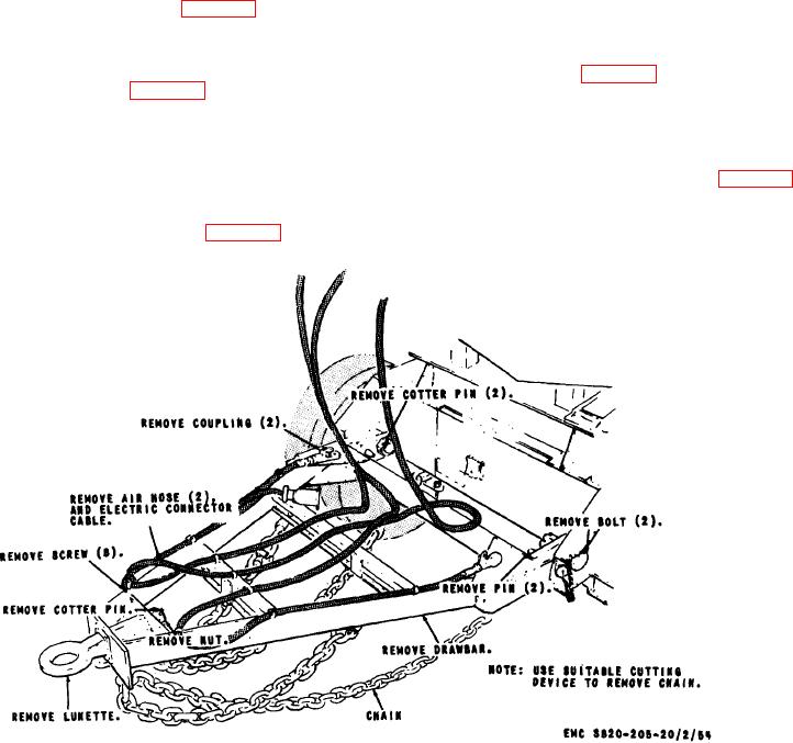
Figure 58. Drawbar, air hose, fittings, safety chain, and lunette, removal and installation.
ACO 8157A 85