
and bracket from the unit as instructed on figure 62.
b. Disassembly. Disassemble the feeder jumper
b. Disassembly. Disassemble the main power
reel and bracket assembly as illustrated on figure 63.
cable reel and bracket as illustrated on figure 65.
c. Cleaning, Inspection, and Repair. Clean and
c. Cleaning, Inspection, and Repair. Clean and
inspect all parts. Repair or replace a defective or
inspect all parts. Repair or replace a defective or
damaged part as necessary.
damaged part as necessary.
d. Reassembly. Reassemble the feeder jumper
d. Reassembly.
Reassemble the main power
reel and bracket as illustrated on figure 63.
cable reel and bracket assembly illustrated on figure 65.
e. Installation. Install the feeder jumper reel and
e. Installation. Install the main power cable reel
bracket assembly in reverse of the instructions on figure
and bracket assembly on the unit in reverse of the
instructions on figure 64.
126. Pushbutton Switches
125. Main Power Cable Reel and Bracket Assembly
a. Removal. Remove the pushbutton switches
a. Removal. Remove the main power cable reel
from the control box as instructed on figure 66.
and bracket assembly from the unit as instructed on
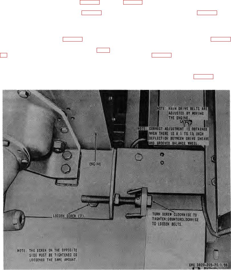
Figure 60. Main drive belt, adjustment.
AGO 8157A
89