
c. Cleaning, Inspection, and Repair. Clean and inspect all parts. Repair or replace defective or damaged parts
as necessary.
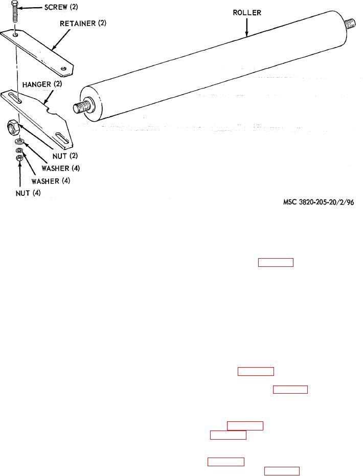
d. Reassembly. Reassemble the return roller assembly as illustrated on figure 96.
e. Installation. Install the return roller assembly in reverse of instructions on figure 95.
Section VIII. FRAME ASSEMBLY
165. General
The frame consists of the platforms, ladders, pintle hook and bracket, leveling jacks and supports, power cable and reel
assembly, and toolbox.
166. Leveling Jacks and Supports
a. Removal. Remove the leveling jacks and supports as instructed on figure 97.
b. Cleaning and Inspection. Clean and inspect all parts. Replace all damaged or defective parts.
c. Installation. Install the leveling jacks and support in reverse of instructions on figure 97.
167. Pintel Hook and Bracket
a. Removal. Remove the pintle hook and bracket as instructed on figure 98.
b. Disassembly. Disassemble the pintle hook as illustrated on figure 99.
c. Cleaning, Inspection, and Repair. Clean and inspect all parts. Replace or repair damaged or defective parts
as necessary.
d. Reassembly. Reassemble the pintle hook as illustrated on figure 99.
e. Installation. Install the pintle hook and bracket in reverse of instructions on figure 98.
AGO 8156A
120