
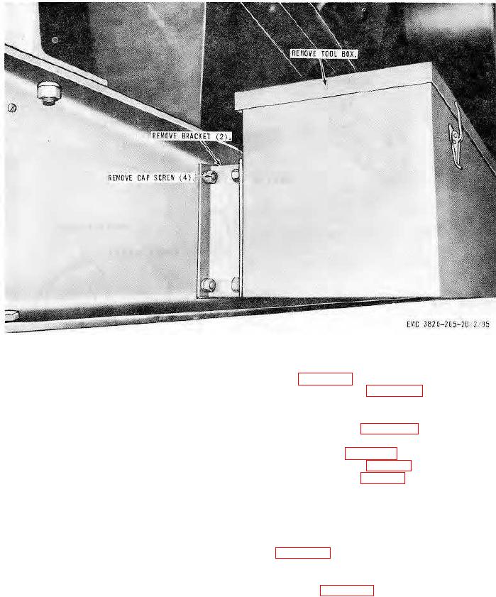
Figure 100. Toolbox, removal, and installation.
(3) Remove the power cable reel assembly as instructed on figure 101.
b. Disassembly. Disassemble the power cable reel assembly as illustrated on figure 102.
c. Cleaning, Inspection, and Repair. Clean and inspect all parts. Repair or replace all damaged or defective
parts.
d. Reassembly. Reassemble the power cable reel assembly as illustrated on figure 102.
e. Installation.
(1) Install the power cable reel assembly in reverse of instructions on figure 101.
(2) Install the electrical conduit on the power cable reel mounting bracket (par. 125).
(3) Install the clearance lights on the power cable reel mounting bracket (par. 125).
170. Ladders and Platforms
a. Removal.
(1) Disconnect the electric power supply (TM 5-3820-205-10/2) before removing the ladders or platforms.
(2) Remove the ladders and platforms as instructed on figure 103.
b. Cleaning and Inspection. Clean and inspect all parts. Replace all damaged or defective parts.
c. Installation.
(1) Install the platforms and ladders in reverse of instructions on figure 103.
(2) Connect the electrical power supply after installation of platforms and ladders (TM 5-3820-205-10/2).
AGO 8156A
124