
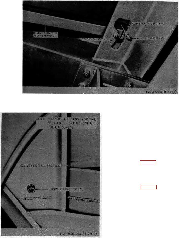
Figure 5-Continued
35. Bogie and Rear Axle Assembly
a. Removal.
(1) Disconnect the brake airlines (TM 5-8820-5-
20/2).
(2) Using a suitable lifting device lift and crib
the rear portion of the crusher assembly.
(3) Refer to figure 6 and remove the bogie and
rear axle assembly from the unit.
b. Installation.
(1) Refer to figure 6 and install the bogie and
rear axle assembly on the unit.
(2) Using a suitable lifting device lift rear
portion of the crusher assembly and
remove the cribbing.
(3) Lower the rear portion of the crusher
assembly.
(4) Connect the brake airlines (TM 5-3820-20-
20/2).
Figure 5-Continued.
AGO 8456A
23