
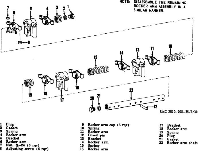
Figure 21. Rocker arm assembly, exploded view.
Section XI. CYLINDER HEAD ASSEMBLY
where its modified force against the head of the piston
76.
General The engine has two cylinder head
continues well through the power stroke.
assemblies.
77.
Cylinder Head
Assembly
Removal
and
Each cylinder head assembly covers three
Disassembly
cylinders. The cylinder head assemblies contain the
intake and exhaust valves, the rocker arm assembly,
a.
Removal.
and the energy cells. The cylinder heads are water-
(1)
Remove the engine housing (TM
cooled and also have oil galleries which lubricate the
53820-20-20/2).
rocker arm mechanism. The energy cells are located in
(2)
Remove the valve covers (TM 5-
the cylinder head directly opposite the fuel injector
3820205-20/2).
nozzle. The fuel is injected by the fuel injector into the
combustion chamber and energy cell. The fuel which is
(3)
Remove the fuel injector assemblies
in the combustion chamber is ignited and starts the
(TM 5-3820-20-20 2).
combustion. The air and fuel in the energy cell likewise
(4)
Remove the water manifold (TM 5
ignites, but due to the design of the cell the pressure is
380-205-20./2).
trapped and is permitted to expand only through the
metered opening, back to the combustion chamber
AGO 3456A
52