
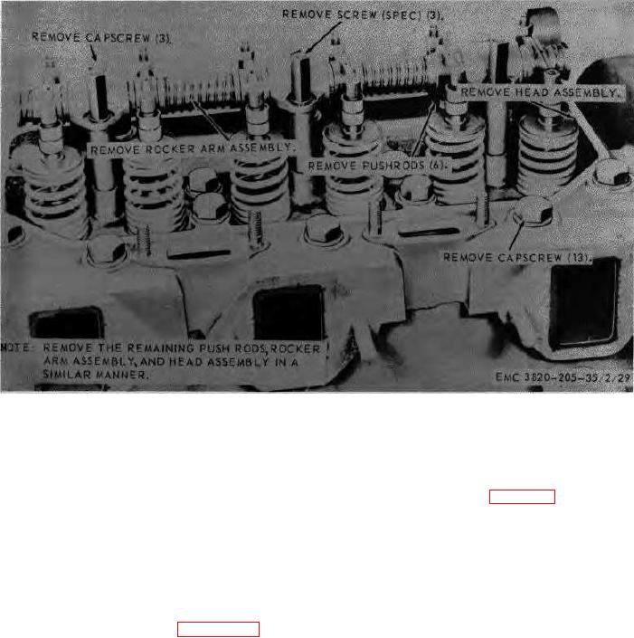
Figure 20. Rocker arm assembly, push rods, and cylinder head assembly, removal and installation.
reassemble the rocker arm assembly in the reverse
(5)
Inspect the springs for cracks, breaks,
order.
or loss of tension.
b.
Installation.
(6)
Inspect the adjusting screws for wear
at the contact surface.
(1)
Refer to figure 20 and install the push
rods and rocker arm assembly on the
(7)
Inspect all threaded parts for worn or
engine.
damaged threads.
(2)
Adjust the rocker arms and install the
(8)
Replace or repair all defective parts
cylinder head covers (TM 5382-205-
as necessary.
20/2).
75.
Rocker Arm
Assembly
Reassembly
and
(3)
Install the engine housing (TM 5-
Installation
3820-205-20/2).
Reassembly.
Refer to figure 21 and
a.
AGO 3456A
51