
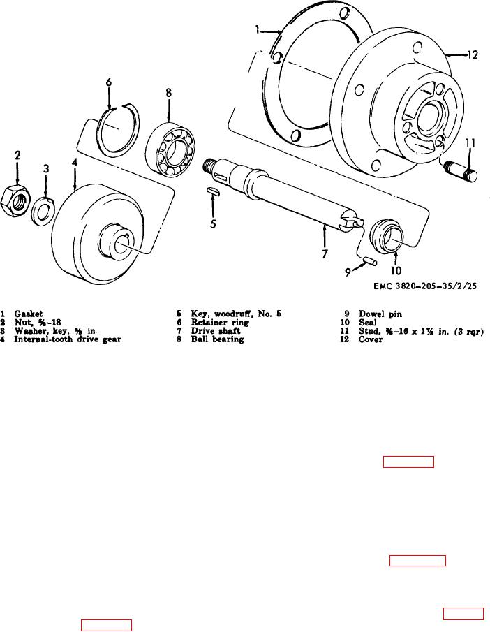
Figure 18. Injection pump drive shaft assembly, exploded view.
injection pump drive gear in the
70.
Injection Pump Drive Shaft and Drive Gear
reverse order.
Assemblies Cleaning, Inspection, and Repair
Note. Install the washer (10), bearing
Cleaning. Clean all parts in an approved
a.
(9), spacer (8), and bearing (7) on the
cleaning solvent and dry thoroughly.
shaft (6) and install the assembled
b.
Inspection and Repair.
shaft in the housing (12).
(1)
Inspect the bearings for looseness,
(2)
Refer to figure 18 and reassemble the
cracks, or wear. Replace defective
injection pump drive shaft in the
reverse order.
(2)
Inspect the gears for chipped,
Note. Install the bearing (8) on the
cracked, worn or damaged teeth.
shaft (7) and install the assembled
Replace a defective gear.
shaft and bearing in the cover (12).
(3)
Inspect all threaded parts for burred or
b.
Installation.
damaged threads.
Replace a
(1)
Refer to figure 16 and install the
defective part as necessary.
injection pump drive shaft and drive
71.
Injection Pump Drive Shaft and Drive Gear
gear assembly on the engine.
Assemblies Reassembly and Installation
(2)
Install the fuel injection pump and
a.
Reassembly.
governor assembly (par. 67).
(1)
Refer to figure 19 and reassemble the
AGO 3456A
49