
TM 5-3820-233-35/1
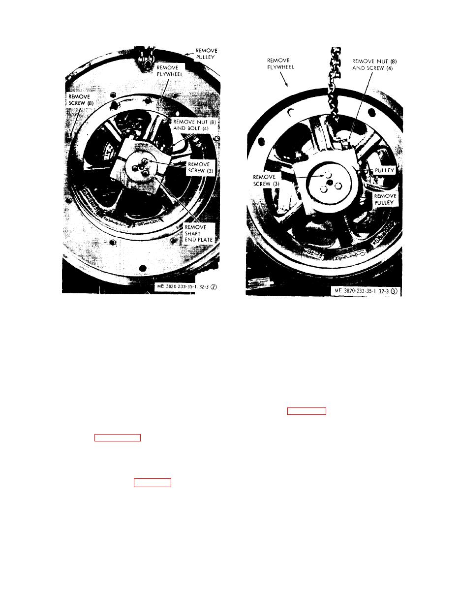
STEP 3. REMOVE RH FLYWHEEL AND PULLEY.
STEP 2. REMOVE LH FLYWHEEL AND PULLEY.
Figure 32-3 (3). Continued.
Figure 32-3 (2). Continued.
k. Tension Spring and Rod Reassembly.
(3) Lift the adjustable toggle seat into
Reassemble tension spring and rod (32
position. Install the toggle seat supports (90)
and secure them to crusher base with bolts
through 39) as illustrated on figure 32-2.
(88) and nuts (87 and 88).
l. Flywheel and Pulleys Reassemly
(1) Refer to figure 32-3 and install fly-
(4) Install shim support bracket (86)
wheels and pulleys.
and secure it to crusher base with capscrews
(85), lockwashers (84) and nuts (83).
(2) Fill side bearing housings and pit-
man with lubricant. Grease side bearing as-
(5) Install shims (69 through 72) and
cover plate (fig. 32-6).
semblies (Operator's Manual).
m. Adjustable Toggle Seat Reassembly
(6) Slowly release hydraulic jack pres-
sure, and remove hydraulic jack.
(1) Install and position hydraulic jack as
shown on figure 32-5. Push pitman forward
n.Adjustments
with the hydraulic jack.
(1) Adjust crusher discharge opening
(2) Position adjustable toggle seat un-
(Operator's Manual).
derneath crusher base. Insert a light chain
through shim slots and attach it to adjusta-
(2) Make the proper drive belt tension
ble toggle seat (93, fig. 32-2).
adjustments (Operator's Manual).
4-21
