TM 5-3820-233-35/2
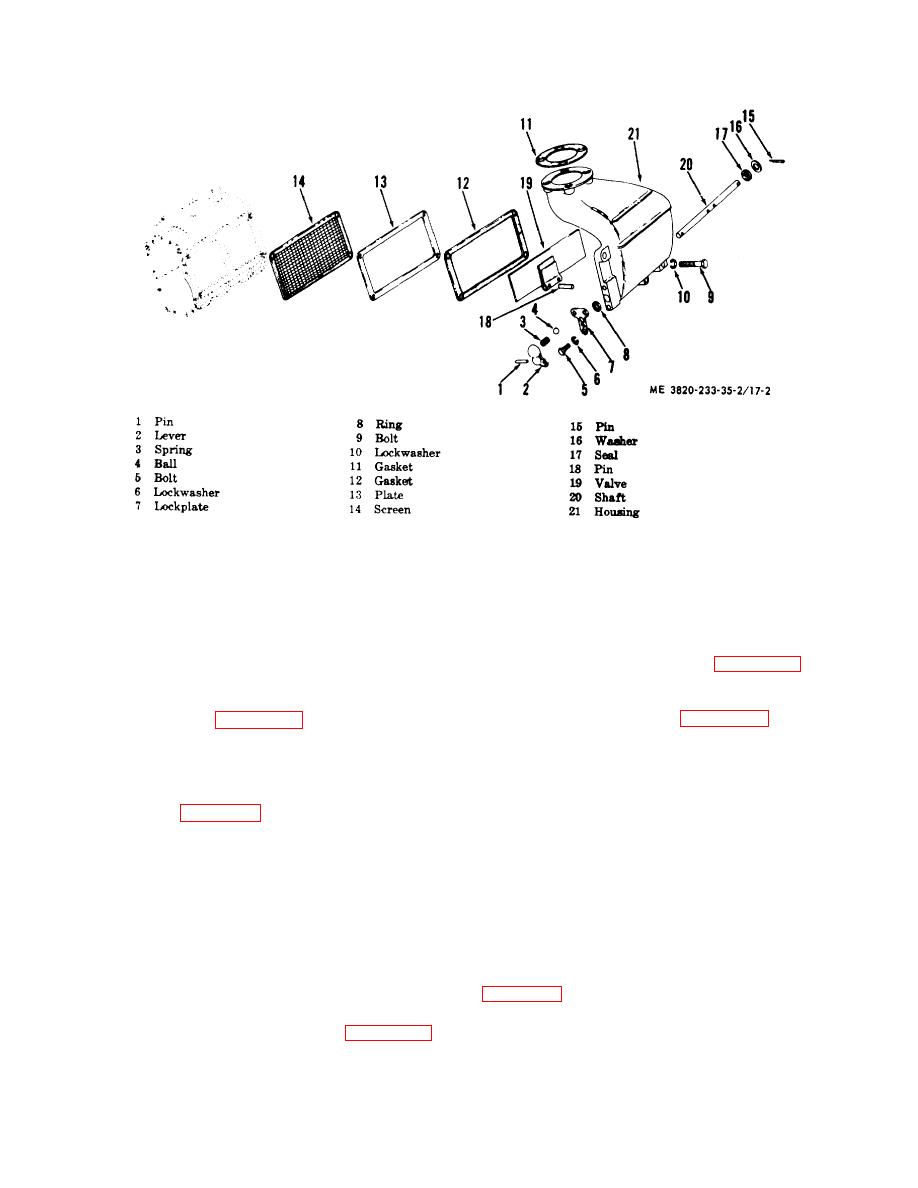
Figure 17-2. Air inlet housing, exploded view.
Note. Installing a .003 inch shim in
(c) Torque bearing retainer bolts (26
back of a rotor gear will turn the
and 41) to 7-9 lb.-ft.
rotor .001 inch.
(d) Torque water pump drive coupling
retaining bolt (39) to 19, lb.-ft.
(j) Determine the minimum clearances
(e) Torque end plate cover (37)
at points "A" and "B" shown on figure 17-5. Measure
mounting bolts (35) to 13-17 lb.-ft.
clearances at the ends of each lobe, making 12
(f) Before installing the blower rotor
measurements in all.
timing gears (24), check rotor-to-end plate and rotor-to-
(k) Refer to figure 17-5 and measure
housing clearances. See figure 17-5.
the clearance between each rotor lobe and the blower
(g) Torque rotor timing gear retaining
housing at both the inlet and outlet side. Twelve
bolts (20) to 55-65 lb.-ft.
measurements are required.
(h) After the blower rotors (33 and 34)
(l) Torque the plate to hub bolts (14) to
and timing gears (24) are installed, time the blower
25-30-ft. lb.
rotors as shown on figure 17-5.
(m) Torque plate to gear bolts (11) to
25-30-ft. lb.
Note. When the right hand helix gear
(n) Measure the runout of the rotor
is moved out, the right hand helix
drive hub splines with an indicator. The spline runout
rotor will turn counterclockwise
must not exceed .020 inch total indicator reading.
when viewed from the gear end.
(o) Torque end plate cover (7)
When the left hand helix gear is
mounting bolts to 13-17-ft. lb.
moved out, the left hand helix rotor
will turn clockwise when viewed from
(2) Reassemble the blower drive assembly in the
the gear end.
reverse of the numerical sequence as illustrated on
(i) If more or less shims are required to
Note. Torque the hub nut (10) to 50-
produce the desired clearance indicated on figure 17-5,
60 ft lb.
both gears must be removed from the rotors.
3-18


