ENGINE:
7. Disconnect and cap air intake hose and
ENGINE REMOVAL:
remove air cleaner assembly. Disconnect ex-
1. Park machine on level surface, set park-
haust pipes at the manifolds.
ing brake, lower blade and securely block machine.
8. Remove transmission fill pipe from
2. Remove rear fenders and engine side plates.
engine lifting eye.
3. Remove radiator (refer to COOLING SYSTEM).
9. Install a suitable lifting device on engine
and support engine weight. Remove rear engine
mounting bolts.
Note: The terms "front" and "rear" when refer-
ring to a machine component are determined by
sitting in the operator's seat and facing toward
front of machine.
10. Remove mounting bolts securing fly-
wheel housing to transmission side plates.
11. Remove bolts from the transmission to
engine mounting flange.
12. The engine may now be carefully moved
to rear of the, machine to clear the hydraulic
tank, and raised out of the machine.
INSTALLATION:
1. To Install engine, reverse removal procedure.
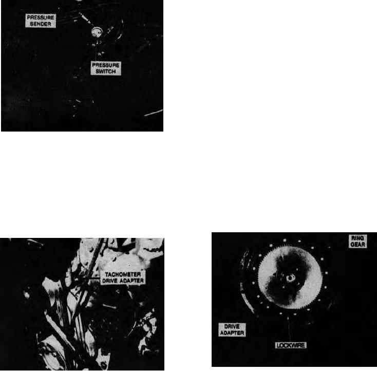
Engine Oil Pressure Sender and Switch
2. Care must be taken when coupling the
engine to the transmission, not to damage the
4. Close fuel shut-off valve at fuel tank and
fibre ring gear on engine flywheel.
disconnect and cap fuel supply and fuel return
3. If installing a new ring gear on the engine
hoses at engine.
flywheel, check to see that it fits on the con-
5. Disconnect and label all electrical con-
verter drive ring before mounting.
nections at engine. Remove engine temperature
4. Mount the fibre ring gear on engine fly-
sending unit from the engine.
wheel, install bolts and torque evenly to 21
6. Disconnect throttle and tachometer
ft-lbs (3 m-kg).
cables at engine.
Tachometer Cable Drive Adapter
K300
Rev. 760501
40-5.2

