
TESTING AND ADJUSTMENT
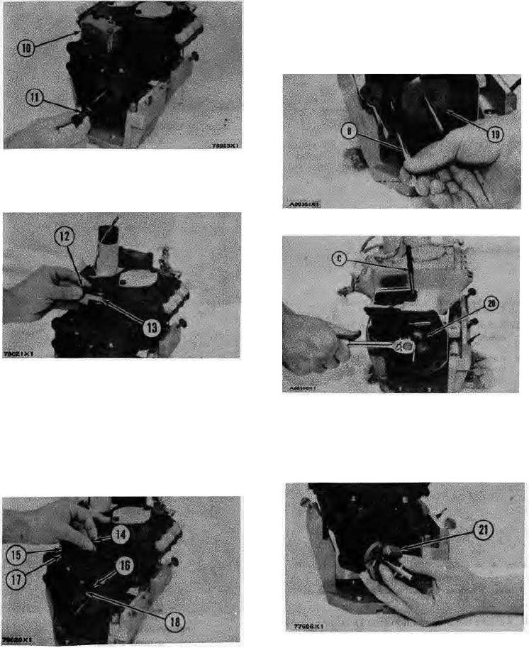
10. Remove the cover (10) from the pump housing.
15. Remove the shield (19) from the camshaft with bar
(B).
CAUTION: Pull on the shield only a small amount in each
location, so it will not have distortion or damage. The
shield is staked in place and can be damaged when
removed. If the shield is damaged it must be replaced.
REMOVING COVER AND THRUST COLLAR
10. Cover. 11. Thrust collar.
11. Loosen the two bolts (12) that hold the torque spring
assembly (13) and remove it from the pump housing.
REMOVING SHIELD
19. Shield. B. 5P302 Bar.
REMOVING TORQUE SPRING
12. Bolts (two). 13. Torque spring assembly.
REMOVING BOLTS
12. Remove the pin (14) from the pump housing.
20. Bolts (three). C. 3P1544Timing Pin.
13. Remove the screw (15) and the nut (17) from the
16. Install the timing pin (C) to hold the camshaft.
pump housing.
17. Remove the bolts (20) that hold the flyweight
14. Remove the ring that holds the lever and remove the
assembly to the camshaft.
lever (18) from the dowel (16).
REMOVING FLYWEIGHT ASSEMBLY
(Typical Example)
REMOVING GOVERNOR PARTS
14. Pin. 15.Screw. 16.Dowel. 17.Nut. 18.Lever.
21. Flyweight assembly.
66