TESTING AND ADJUSTMENT
6. Add load on the engine slowly until the continuity light
just comes on. This is the balance point.
7. Make a record of the speed at the balance point.
8. Repeat' Step 6 several times to make sure that the
reading is correct.
9. Stop engine. Make a comparison of the records from
Steps 5 and 7 with the information from the RACK
SETTING INFORMATION.
10. If the balance point is correct, the fuel system is
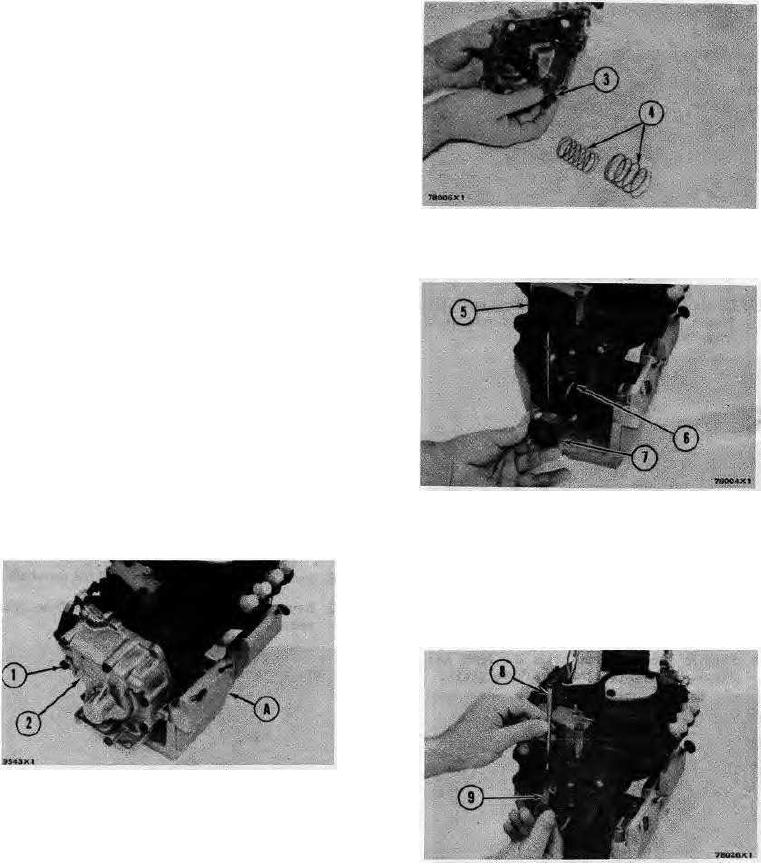
REMOVING SPRINGS AND SEAT
working correctly. If the balance point is not correct,
3. Seat. 4. Springs.
adjust the, high idle rpm until you get the correct
balance point.
5. Remove the seat (7) from the shaft.
PROCEDURE FOR INSTALLATION OF DASHPOT
GOVERNOR
Tools Needed: 2P8315 Bracket Assembly.
5P302 Bar.
3P1544 Timing Pin.
5P301 Driver.
Remove Governor
1. Install the fuel injection pump housing on the bracket
assembly (A).
REMOVING GOVERNOR PARTS
2. Remove the bolts (1) that hold the governor housing
5. Cover. . Spring. 7. Seat.
(2) to the fuel injection pump housing.
6. Remove the spring (6) from the shaft.
7. Remove the cover (5) from the pump housing.
8. Remove the shaft (8) and the lever (9) from the pump
housing.
GOVERNOR HOUSING
1. Bolts. 2. Governor housing. A. 2P8315 Bracket
Assembly.
3. Remove the governor housing (2).
REMOVING SHAFT AND LEVER
4. Remove two springs (4) and the seat (3) from the
8. Shaft. 9. Lever.
governor housing. Remove springs (4) from seat (3).
9. Remove the thrust collar (11) from the shaft. 65
65

