
3208 INDUSTRIAL AND MARINE ENGINES
DISASSEMBLY AND ASSEMBLY
FUEL TRANSFER PUMPS
8. Install the four bolts (7) that hold the body
to the housing.
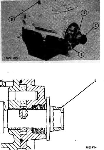
9. Put tool (D) in position to keep the cam-
shaft from turning.
10. Put the sleeve (6) on the camshaft.
11. Tighten the sleeve into position on the shaft
with 4B4280 Washer of tooling (C) approxi-
mately 25 in. (6.4 mm). Tighten the sleeve
the remainder of the way with the 4N3371
Washer until the sleeve is at bottom. The
washer is the washer which is on the
tachometer drive bolt.
CAUTION: Do not hit the sleeve to install. Dam-
age to governor will result.
12. The end play of the camshaft must be
.023 .018 in. (0.58 0.46 mm) after
sleeve (6) is installed.
end by:
a) install fuel injection pump housing
and governor
26