
3208 INDUSTRIAL AND MARINE ENGINES
DISASSEMBLY AND ASSEMBLY
FUEL INJECTION PUMP HOUSING AND GOVERNOR
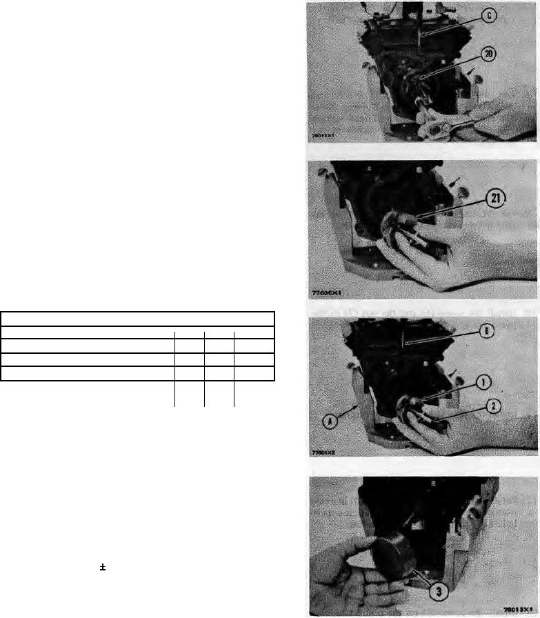
17. Install the timing pin (C) to hold the camshaft.
18. Remove the bolts (20) that hold the fly-
weight assembly to the camshaft.
19. Remove the flyweight assembly (21) from
the camshaft.
20. Remove the timing pin (C) from the pump
housing.
CONNECTION OF GOVERNOR TO FUEL
INJECTION PUMP HOUSING
Tools Needed
A
B
C
2P8315
Bracket Assembly
1
3P1544
Timing Pin
1
5P301
Driver
1
1. Put the fuel injection pump housing on the
bracket assembly (A).
2. Install the timing pin (B) to hold the
camshaft.
3. Put the flyweight assembly (1) in position
on the camshaft.
NOTE: Be sure the pin that holds the shaft (2) is in
position on the back of the flyweight assembly.
4. Install the bolts that hold the flyweight
assembly to the camshaft and tighten to a
torque of 10 2 lb. ft. (1.38 0.28 mkg).
5. Remove the timing pin (B).
6. Put the shield (3) in position over the flyweights.
29