
3208 INDUSTRAIL AND MARINE ENGINES
DISASSEMBLY AND ASSEMLBLY
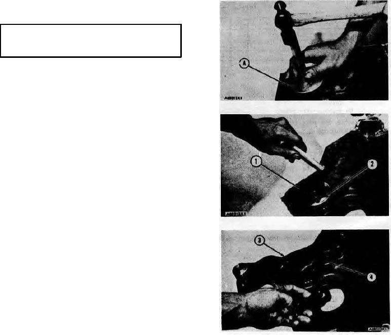
OIL PUMP AND RELIEF VALVE
INSTALL OIL PUMP AND RELIEF
VALVE 12-1304 & 1315
Tools Needed
A
8S2285
Drive Assembly
1
1.
Thoroughly clean all of the parts. Put oil on all
of the parts.
2.
If the bearing was removed from the timing
gear cover, install a/new bearing with tool (A).
3.
Install inner rotor (2) and outer rotor (1) in the
timing gear cover.
4.
Measure the clearance between the rotors with
a feeler gauge. The clearance must be .002 to
.006 in. (0.05 to 0.15 mm). The maximum
permissible clearance is .009 in. (0.23 mm).
NOTE: Make a replacement of both rotors if the
clearance is not correct. The rotors can not be ordered
separately.
5.
Put the plunger and spring in position and push
the guide into the cover with a press until the
lip on the guide is even with the finished
surface on the cover. Make sure the flat
surface on the guide is in alignment with the
setscrew. Tighten the setscrew.
6.
Put cover (3) in position on the timing gear
cover. Install the locks and bolts (4).
end by:
a) install timing gear cover and oil pump
83