
3208 INDUSTRAIL AND MARINE ENGINES
DISASSEMBLY AND ASSEMLBLY
TIMING GEAR COVER AND OIL PUMP
REMOVE TIMING GEAR COVER AND OIL
PUMP (INDUSTRIAL ENGINE) 11-1166 & 1304
Tools Needed
A
8S6692
Water Sleeve Tool
1
start by:
a) remove oil pan
b) remove crankshaft pulley
1.
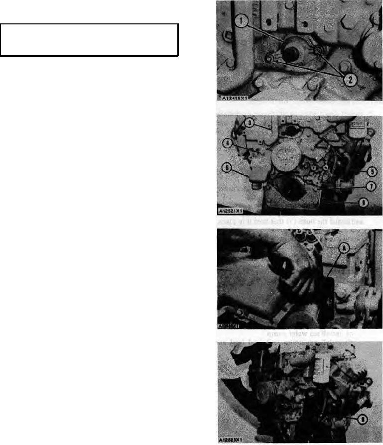
Remove oil pump suction pipe.
2.
Remove two nuts (2) and tachometer drive
housing (I).
3.
Remove the four bolts (7) that hold the front
support (8) to the timing gear cover.
4.
Disconnect water outlet elbow (5) from the oil
cooler.
5.
Disconnect fuel lines from the fuel filter base.
6.
Remove the clamps from the water sleeves in
each cylinder head. Push the sleeves into the
timing gear cover with tool (A).
7.
Remove connector (3).
8.
Remove the bolts (4) that hold the timing gear
cover to the cylinder block. Be sure to remove
the bolt that is behind elbow (6).
Put
identification of the bolts as to their location for
use at assembly.
CAUTION: Be extra careful not to cause damage to the
crankshaft front seal during removal and installation of
the timing gear cover.
9.
Install two 7/16"-14 NC forged eyebolts in the
timing gear cover. Fasten a hoist and remove
timing gear cover (9) and the oil pump from the
dowels on the cylinder block. The weight of the
timing gear cover and oil pump is 136 lb. (62
kg).
80