
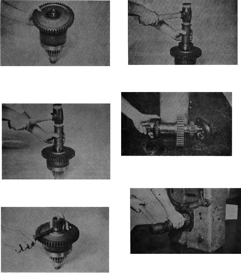
Figure 98
Figure 95
Install low clutch shaft rear bearing.
Install low gear Into clutch drum. Align splines on low gear
Reassembly of the Output Shaft
with Internal teeth of friction discs. Tap gear Into position.
Do not force this operation, Gear splines must be In full
position with Internal teeth of all friction discs.
Figure 99
View of output shaft as it would be positioned in
transmission cace. Note front cone bearing shouldered on
shaft with large diameter of bearing in.
Figure 96
Install low gear outer bearing. NOTE: When in- stalling
the 3rd gear In the 3rd speed clutch a bearing spacer is
used between the Inner and outer 3rd gear bearing.
Figure 100
Position output gear in transmission case with protruding
hub toward front of case. See Fig. 99. Insert output shaft,
gear spacer and taper bearing from front of case and
Figure 97
through output gear. Install front taper bearing cup. Block
Install low gear retainer ring.
output shaft and install rear taper bearing with large
diameter in.