
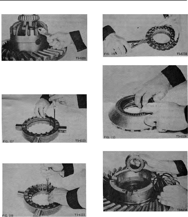
4. Lockwire bolts in pairs (Fig. 106) on axles that use
3. Install holdout ring on drive clutch with snap ring
tapped differential case bolt holes.
pliers (Fig. 109).
FIG. 109
FIG. 106
4. Install spring retainer in driven clutch (Fig. 110).
Reassembly of NoSPIN Differential
NOTE: Lightly lubricate parts of NoSPIN differential
during assembly. Special lubricants are not required
for use with this differential.
1. Install snap ring In Internal groove of spider (Fig.
107).
FIG. 110
FIG. 107
5. Install side gear and spring in differential case half
2. Position center cam In spider, Spread snap ring while
(Fig. 111).
inserting center cam (Fig. 108). Make sure center
cam ring groove is fully engaged by snap ring to
retain center cam.
FIG. 111
FIG. 108
36