
STEERING RELIEF VALVE:
REF.
REF.
NO.
DESCRIPTION
NO.
DESCRIPTION
1
Housing, Relief Valve
10
Spring, Pilot
2
Seal, Relief Body
11
Screw, Adjusting
3
Washer, Back Up
12
Gasket, Cap
4
Ring, Retaining
13
Cap
5
Cylinder
14
Body, Relief
6
Piston
15
Seal, Relief Body
7
Pin, Wire
16
Washer, Back Up
8
Spring, Piston
17
Seal, Body
9
Poppet
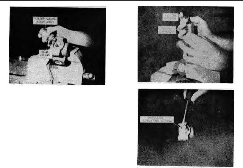
2. Remove body and inspect seal rings.
3. Remove piston spring and piston and cylinder
assembly.
4. Check condition of all valves and seats and
inspect for signs of wear.
5. Reverse procedure for installation. Replace seal
rings on assembly.
6.
After valve is assembled, back pressure
adjusting screw off to prevent excessive system
pressures when valve is replaced on the machine.
Rev. 760501
60-6.3
K300