
heat slowly. The thermostat should start to open at 165
to 175 F. and be fully open at 180 to 185 F. Replace
a defective thermostat.
d. Installation.
(1) Install the thermostats and housing on the
engine in reverse of the instructions on
(2) Fill the cooling system (TM 5-3820205-
10/1).
104. Water Manifold
a. Removal.
(1) Drain the cooling system (TM 5-3820205-
10/1).
(2) Remove the thermostats and housing
(3) Remove the water manifold from the
engine as instructed on figure 39.
b. Cleaning and Inspection. Clean and inspect the
water manifold for any damage and replace as
necessary.
c. Installation.
(1) Install the water manifold on the engine in
reverse of the instructions on figure 39.
(2) Install the thermostats and housing (para.
(3) Fill the cooling system (TM 5-3820205-
10/1).
C
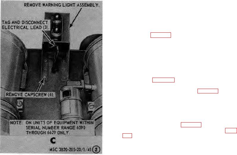
Low 11oil pressure and high water
temperature warning ]lights (on units of
equipment within serial number range 8E50
through 86P29 only)
Figure 41-Continued.
AGO 8157A 66