
Section VII. VALVE COVER AND ROCKER ARM ASSEMBLIES
95. General
b. Clothing and Inspection. Clean and inspect all
The engine intake and exhaust valves Care located in
parts Replace gaskets and damaged parts.
the two cylinder heads. There are three intake and
c. Installation.
three exhaust valves, rocker arms, and rocker arm
(1) Install the two valve covers and breather
adjusting screws located under each valve cover. The
on the engine in reverse of the
valve covers and breather must be removed to perform
instructions on figure 45.
rocker arm adjustment, or to check valve closing when
(2) Install the engine hood (para. 94).
setting ignition timing.
97. Rocker Arms Adjustment
96. Valve Covers and Breather
a. Remove the valve covers and breather (para.
a. Removal.
(1) Remove the engine hood (para. 94).
b. Adjust each of the 6 intake valve rocker arms
(2) Remove the two valve covers and
and the 6 exhaust valve rocker arms as
breather from the engine as instructed on
instructed on figure 46.
c. Install the valve covers and breather (para. 96).
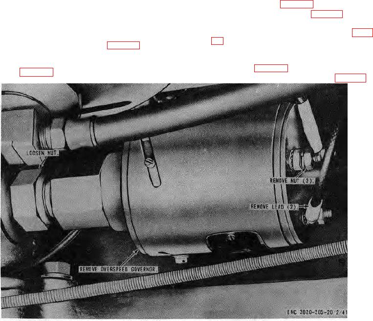
Figure 40. Overspeed governor, removal and installation
AGO 8157A 63