
(5) Install the cover band on the starter in
reverse of the instructions on figure 37.
e. Installation. Install the starter on the engine in
reverse of the instructions on figure 35.
83. Oil Pressure Gage and Sending Unit
a. Removal.
(1) Remove the oil pressure gage from the
instrument panel as instructed on figure.
37.
(2) Remove the oil pressure gage sending
unit from the engine as instructed on
b. Cleaning and Inspection. 'Clean and inspect the
oil pressure gage and sending unit for any damage,
Replace as necessary.
c. Installation.
(1) Install the oil pressure gage sending unit
on the engine in reverse of the
instructions on figure 38.
(2) Install the oil pressure gage on the
instrument panel in reverse of the
instructions on figure 37.
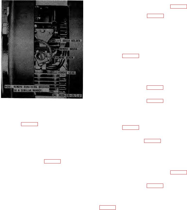
Figure 34. Generator brush, replacement.
84. Water Temperature Gage and Sending Unit
(2) If the starter does not operate, it is
a. Removal.
defective. Replace a defective starter.
(1) Remove the water temperature gage from
b. Removal. Remove the starter from the engine
the instrument panel as instructed on
as instructed on figure 35.
c. Cleaning, Inspection, and Repair.
(2) Remove the water temperature gage
(1) Clean the starter with a cloth dampened
sending unit from the water manifold as
with an approved cleaning solvent.
instructed on figure 39.
(2) Replace a damaged or defective starter
b. Cleaning and Inspection. Clean and inspect the
as necessary.
water temperature gage and sending unit for damage.
d. Brush Replacement.
Replace as necessary.
(1) Remove the cover band from the starter
c. Installation.
as instructed on figure 35.
(1) Install the water temperature gage
(2) Remove the brushes from the starter as
sending unit on the water manifold in
instructed on figure 36.
reverse of the instructions on figure 39.
(3) Inspect the brushes for worn or chipped
(2) Install the water temperature gage on the
condition. Replace brushes if worn to less
instrument panel in reverse of the
than one-half inch in length. Inspect the
instructions on figure 37.
commutator for burning, grooving, and
high mica between segments. Replace a
85. Battery Generator Indicator
defective starter.
a. Removal.
Remove the battery generator
(4) Install new brushes in reverse of the
indicator from the instrument panel as instructed on
instructions on figure 36.
AGO 8157A
58