
A - Coupling rear view
B - Coupling front view
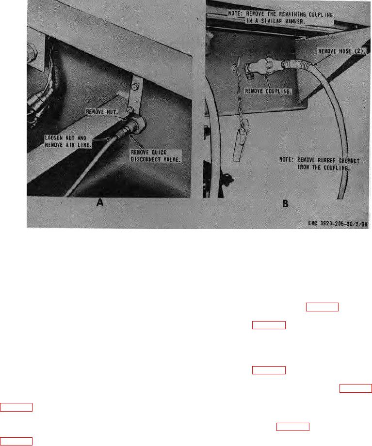
Figure 74. Coupling, hoses and lines, removal and installation.
Section VII. BELT CONVEYOR ASSEMBLIES
149. General
152. Trough Roller Assembly
The feeder belt conveyor is comprised of the head
a. Removal. Remove the trough roller assembly
section, center section, and tail section and is powered
from the unit as instructed on figure 86.
by an electric motor and gear reducer. The feeder belt
b. Disassembly. Disassemble the trough roller as
conveyor receives the material from the reciprocating
illustrated on figure 87.
feeder and rotary elevator and deposits it on the
c. Cleaning, Inspection, and Repair. Clean and
vibrating screen. The under conveyor belt is powered
inspect all parts. Repair damaged parts. Replace worn
by an electric motor and gear reducer. The under
and defective parts.
conveyor belt receives the crushed material from the
d. Reassembly.
Reassemble the trough roller
crusher rolls and deposits the aggregate in the rotary
illustrated on figure 87.
elevator.
e. Installation. Install the trough roller assembly on
the unit in reverse of the instructions on figure 86.
150. Feeder Conveyor Belt Adjustment
Adjust the feeder conveyor belt as instructed on
153. Feeder Conveyor Return Roller Assembly
a. Removal. Remove the return roller from the
151. Under Conveyor Belt Adjustment
unit as instructed on figure 88.
Adjust the under conveyor belt as instructed on
AGO 8157A
106