
actuated by the crank-arm drive. The flow of material
inspect all parts. Repair or replace a defective or
from the feeder to the crusher is controlled by an
damaged gate. Replace a damaged part as necessary.
adjustable gate.
c. Installation. Install the relief chute, extension,
and gate on the unit in reverse of the instructions on
141. Feeder Grizzly and Upper Hopper
a. Removal. Remove the feeder grizzly and upper
hopper from the unit as instructed on figure 77.
143. Reciprocating Feeder Hopper Wear Plates and
b. Cleaning, and inspection. Clean and inspect all
Liners
parts.
Replace a damaged or defective part as
a. Removal.
necessary.
(1) Remove feeder grizzly (para. 141).
c. Installation. Install the feeder grizzly on the unit
(2) Remove the reciprocating feeder hopper
in reverse of the instructions on figure 77.
wear plates and liners from the unit as
instructed on figure 79.
142. Relief Chute, Extension, and Gate
b. Cleaning and Inspection. Clean and inspect all
a. Removal. Remove the relief chute, extension,
parts.
Replace a defective or damaged part as
and gate from the unit as instructed on figure 78.
necessary.
b. Cleaning. Inspection, and Repair. Clean and
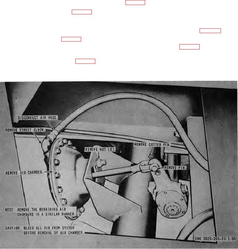
(Serial number range 6550 through 6587)
Figure 70. Air chamber, removal and installation.
AGO 8157A
101