
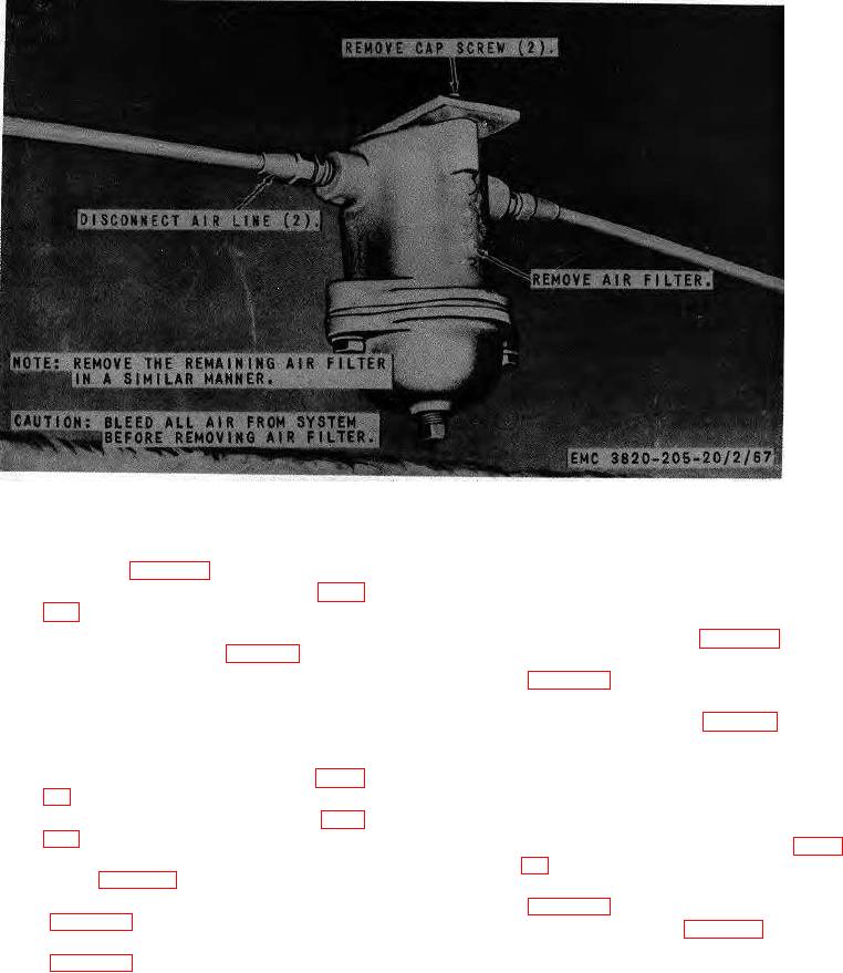
Figure 72. Air filter, removal and installation.
(3) Remove the feeder hopper wear plates
146. Gear Reducer Assembly
and liners (para. 143).
a. Removal.
(4) Remove reciprocating feeder gate (para.
(1) Remove the outer belt guard (TM 53820-
205-10/1).
(5) Remove the feeder hopper assembly from
(2) Remove the drive belt (para. 119).
the unit as instructed on figure 81.
(3) Remove sheave, hub, and guard base
b. Cleaning and Inspection. Clean and inspect all
parts, Replace a defective or damaged part as
(4) Remove the gear reducer assembly from
necessary.
the unit as instructed on figure 82.
c. Installation.
b. Cleaning and Inspection. Clean and inspect all
(1) Install the feeder hopper assembly on the
parts.
Replace a damaged or defective part as
unit in reverse of the instructions on figure
necessary.
c. Installation.
(2) Install the reciprocating feeder gate (para.
(1) Install the gear reducer assembly on the
unit in reverse of the instructions on figure
(3) Install the feeder hopper wear plates and
liners (para. 143).
(2) Install the sheave, hub, and guard base
(4) Install feeder grizzly and upper hopper
(3) Install the drive belt (para. 119).
(5) Install the relief chute and extension
(4) Install the outer belt guard (TM 53820-
205-10/1).
AGO 8157A
104