
CHAPTER 4
ENGINE MAINTENANCE INSTRUCTIONS
Section I. MANUAL AND MECHANICAL CONTROLS AND INSTRUMENTS
54. General
The location and purpose of the controls and instruments are given in TM 5-3820-205-10/2.
55. Engine Clutch Levers
a.
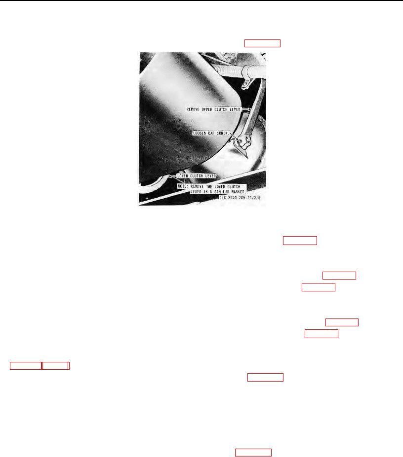
Removal. Remove the two engine clutch levers as instructed on figure 10.
Figure 10. Engine clutch levers, removal and installation.
b.
Cleaning and Inspection. Clean and inspect all parts. Replace if necessary.
c.
Installation. Install the two engine clutch levers in reverse of instructions on figure 10.
56. Throttle Control Lever
a.
Removal.
(1)
Disconnect the throttle control cables from the fuel injection pump as instructed on figure 11.
(2)
Remove the throttle control lever from the instrument panel as instructed on figure 12.
b.
Cleaning and Inspection. Clean and inspect all parts for damage. Replace as necessary.
c.
Installation.
(1)
Install the throttle control lever on the instrument panel in reverse of instructions on figure 12.
(2)
Connect the throttle control cables to the fuel injection pump as instructed on figure 11.
57. Tachometer-Hourmeter and Drive
a. Removal. Remove the tachometer-hour-meter and drive from the instrument panel and engine as instructed
b.
Disassembly. Disassemble the tachometer drive as illustrated on figure 13.
c.
Cleaning, Inspection, and Repair.
(1)
Clean all parts in an approved cleaning solvent and dry thoroughly.
(2) Inspect the tachometer-hourmeter for broken glass, and defective drive cable. Replace a defective
tachometer-hourmeter and drive cable.
(3) Inspect the tachometer drive for worn, damaged, or defective parts. Replace or repair worn, damaged, or
defective parts as necessary.
d.
Reassembly. Reassemble the tachometer drive illustrated on figure 13.
AGO 8156A
25