
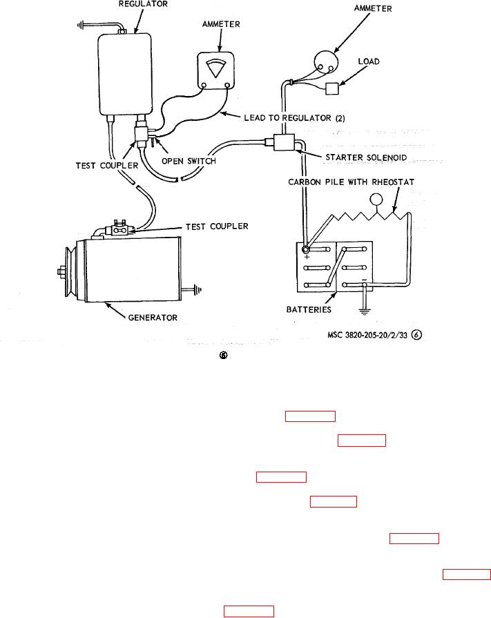
Figure 33--Continued.
89.
Battery Generator Indicator
a. Removal. Remove the battery generator indicator as instructed on figure 38.
b. Cleaning and Inspection. Clean and inspect the battery indicator gage for damage. Replace as necessary.
c. Installation. Install the battery generator indicator in reverse of instructions on figure 38.
90.
Overspeed Governor
a. Removal. Remove the overspeed governor as instructed on figure 41.
b. Cleaning and Inspection. Clean and inspect the overspeed governor for damage. Replace a damaged governor.
c. Installation. Install the overspeed governor in reverse of instructions on figure 41.
91.
Safety Switch and Water Temperature Sending Unit
a. Removal. Remove the water temperature sending unit and safety switch as instructed on figure 42.
b. Cleaning and Inspection. Clean and inspect the safety switch and water temperature sending unit for damage.
Replace as necessary.
c. Installation. Install the water temperature sending unit and safety switch in reverse of instructions on figure 42.
92.
Starter Switch
a. Removal. Remove the starter switch as instructed on figure 38.
AGO 8156A
54