
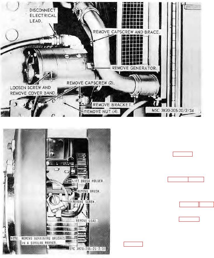
Figure 34. Generator and mounting bracket, removal and installation.
b. Cleaning and Inspection. Clean and inspect
the starter switch for defects. Replace as
required.
c. Installation. Install the starter switch in
reverse of instructions on figure 38.
93. Engine Wiring and Warning Lights
a. Wiring.
(1) Removal. Remove the engine
wiring as instructed on figures 38 and 42.
(2) Cleaning, inspection, and repair.
Clean and inspect the engine wiring. Repair or
replace as necessary.
(3) Installation. Install the engine wiring
in reverse of instructions on figures 38 and 42.
b. Warning Lights.
(1) Removal. Remove the warning light
assembly as instructed on C, figure 42.
(2) Cleaning, inspection, and repair.
Clean and inspect. Repair as necessary.
(3) Installation. Install the warning light
assembly in the reverse of the instructions on C,
Figure 35. Generator brush, replacement.
Figure 35. Brush replacement and installation
AGO 8156A
55