
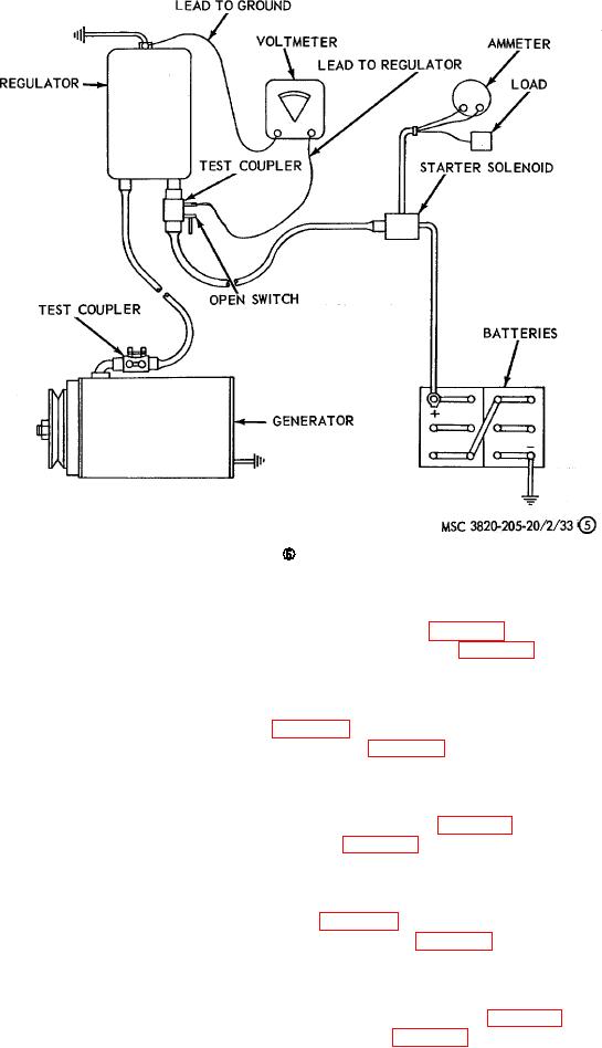
Figure 33--Continued.
(5) Install the cover band on the starter in reverse of the instructions on figure 36.
e. Installation. Install the starter on the engine in reverse of the instructions on figure 36.
87.
Oil Pressure Gage and Sending Unit
a. Removal.
(1) Remove the oil pressure gage as instructed on figure 38.
(2) Remove the oil pressure gage sending unit as instructed on figure 39.
b. Cleaning and Inspection. Clean and inspect the oil pressure gage and sending unit for any damage. Replace as
necessary.
c. Installation.
(1) Install the oil pressure gage sending unit in reverse of instructions on figure 39.
(2) Install the oil pressure gage in reverse of instructions on figure 38.
88.
Water Temperature Gage and Sending Unit
a. Removal.
(1) Remove the water temperature gage as instructed on figure 38.
(2) Remove the water temperature gage sending unit as instructed on figure 40.
b. Cleaning and Inspection. Clean and inspect the water temperature gage and sending unit for damage. Replace
as required.
c. Installation.
(1) Install the water temperature gage sending unit in reverse of instructions on figure 40.
(2) Install the water temperature gage in reverse of instructions on figure 38.
AGO 8156A
53