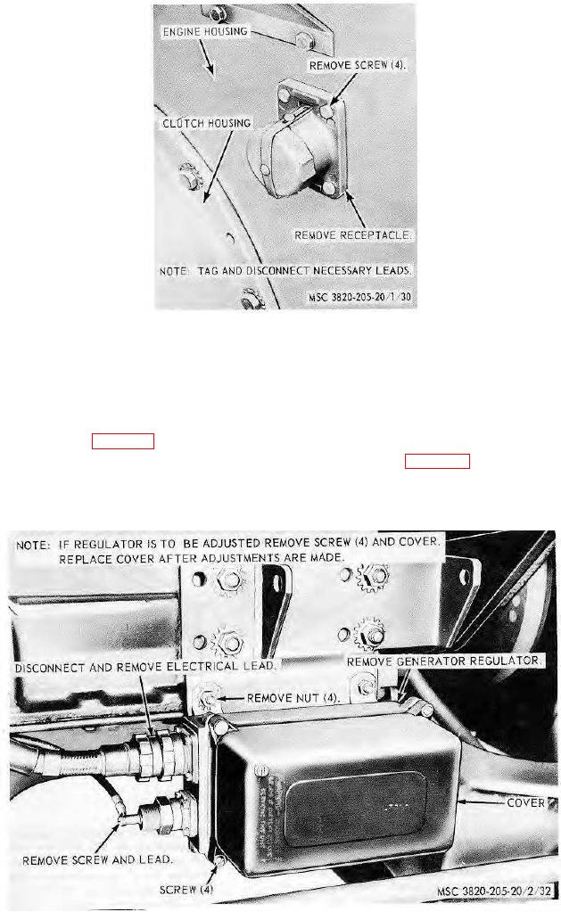
Figure 31. Battery charging receptacle, removal and installation.
between the core residual brass pin and the armature. Adjust the air gap adjusting screw to obtain the correct voltage
regulator air gap of 0.084 inch.
(h) Adjust the current regulator air gap to 0.115 inch in the same manner as the voltage regulator unit was
adjusted, described in (g) above.
(2) Electrical adjustments. Install set of test adapters.
Note. Refer to 3, figure 33 and polarize the generator.
(a) Cutout relay closing voltage. With voltmeter connected as shown on 4, figure 33, start the engine and slowly
increase speed until the cutout relay contact points close. Observe voltage reading at which this occurs. It
should be between 28 and 32 volts. If adjustment is necessary, turn cutout relay adjusting screw clockwise to
increase or
Figure 32. Generator regulator, removal and installation.
AGO 8156A
48

